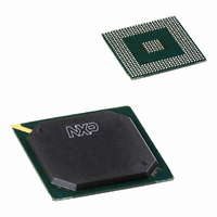
PNX1501E,557 NXP Semiconductors, PNX1501E,557 Datasheet - Page 533

PNX1501E,557
Manufacturer Part Number
PNX1501E,557
Description
IC MEDIA PROC 266MHZ 456-BGA
Manufacturer
NXP Semiconductors
Datasheet
1.PNX1502EG557.pdf
(828 pages)
Specifications of PNX1501E,557
Applications
Multimedia
Core Processor
TriMedia
Controller Series
Nexperia
Interface
I²C, 2-Wire Serial
Number Of I /o
61
Voltage - Supply
1.14 V ~ 1.26 V
Operating Temperature
0°C ~ 85°C
Mounting Type
Surface Mount
Package / Case
456-BGA
Lead Free Status / RoHS Status
Lead free / RoHS Compliant
Program Memory Type
-
Ram Size
-
Other names
935274728557
PNX1501E
PNX1501E
PNX1501E
PNX1501E
Available stocks
Company
Part Number
Manufacturer
Quantity
Price
Company:
Part Number:
PNX1501E,557
Manufacturer:
NXP Semiconductors
Quantity:
10 000
- Current page: 533 of 828
- Download datasheet (8Mb)
Philips Semiconductors
Volume 1 of 1
PNX15XX_SER_3
Product data sheet
3.3 Register Programming Guidelines
3.4 Serial Data Framing
Clocks are required to be running during HW/SW reset because synchronous reset is
used to initialize the logic. The unique feature with Audio is that unlike all other blocks
in the system, the Audio blocks default to the external clock source on any reset. If
the external clock does not exist when a HW reset is applied, then the logic is left
uninitialized without any indication.
Software needs to ensure that the cap_enable bit (bit 30, AI_CTL) is programmed
after all the other registers have been programmed to ensure proper functionality.
Disabling and re-enabling capture
Here is a brief discussion on how the audio in block works if for some reason software
needs to disable the capture and consequently re-enable it. The Audio Input module
is continuously capturing and transferring data to memory through the adapter in the
system. The adapter threshold should be suitably set to satisfy the system latency
requirements. Once the adapter FIFO reaches the threshold, it will initiate a transfer
to memory. This behavior will continue until the capture is disabled. Once the capture
is disabled, the Audio In block will issue a FLUSH to the adapter so that it can flush its
FIFO and hence all the pertinent data that would reach memory. However, it must be
understood that disabling capture is not the same as applying software reset. Even
though capture is disabled, all the internal DMA state machines have pointers
pointing to addresses in memory corresponding to the transaction that was just
completed. So if the software intends to re-enable capture from scratch with new
pointers, there needs to be a software reset performed between disabling and re-
enabling the capture, along with optional reprogramming of the registers. Failure to
do a software reset will result in the Audio Input module behaving as though the
previous transaction is continuing with all the previous pointers active.
The Audio In unit can accept data in a wide variety of serial data framing conventions.
Figure 3
and EARLYMODE=0, a frame is defined with respect to the positive transition of the
WS signal as observed by a positive clock transition on SCK. (See
data bit sampled on positive SCK transitions has a specific bit position—i.e., once the
clock edge detects the WS transition, the next sample will be data bit position 0.
illustrates the notion of a serial frame. If POLARITY = 1, CLOCK_EDGE = 0,
Rev. 3 — 17 March 2006
© Koninklijke Philips Electronics N.V. 2006. All rights reserved.
PNX15xx Series
Chapter 16: Audio Input
Section
4..) Each
16-7
Related parts for PNX1501E,557
Image
Part Number
Description
Manufacturer
Datasheet
Request
R
Part Number:
Description:
Manufacturer:
NXP Semiconductors
Datasheet:
Part Number:
Description:
Digital Signal Processors & Controllers (DSP, DSC) MEDIA PROCESSOR PNX15XX/266MHZ
Manufacturer:
NXP Semiconductors
Datasheet:

Part Number:
Description:
IC MEDIA PROC 266MHZ 456-BGA
Manufacturer:
NXP Semiconductors
Datasheet:
Part Number:
Description:
NXP Semiconductors designed the LPC2420/2460 microcontroller around a 16-bit/32-bitARM7TDMI-S CPU core with real-time debug interfaces that include both JTAG andembedded trace
Manufacturer:
NXP Semiconductors
Datasheet:

Part Number:
Description:
NXP Semiconductors designed the LPC2458 microcontroller around a 16-bit/32-bitARM7TDMI-S CPU core with real-time debug interfaces that include both JTAG andembedded trace
Manufacturer:
NXP Semiconductors
Datasheet:
Part Number:
Description:
NXP Semiconductors designed the LPC2468 microcontroller around a 16-bit/32-bitARM7TDMI-S CPU core with real-time debug interfaces that include both JTAG andembedded trace
Manufacturer:
NXP Semiconductors
Datasheet:
Part Number:
Description:
NXP Semiconductors designed the LPC2470 microcontroller, powered by theARM7TDMI-S core, to be a highly integrated microcontroller for a wide range ofapplications that require advanced communications and high quality graphic displays
Manufacturer:
NXP Semiconductors
Datasheet:
Part Number:
Description:
NXP Semiconductors designed the LPC2478 microcontroller, powered by theARM7TDMI-S core, to be a highly integrated microcontroller for a wide range ofapplications that require advanced communications and high quality graphic displays
Manufacturer:
NXP Semiconductors
Datasheet:
Part Number:
Description:
The Philips Semiconductors XA (eXtended Architecture) family of 16-bit single-chip microcontrollers is powerful enough to easily handle the requirements of high performance embedded applications, yet inexpensive enough to compete in the market for hi
Manufacturer:
NXP Semiconductors
Datasheet:
Part Number:
Description:
The XA-S3 device is a member of Philips Semiconductors? XA(eXtended Architecture) family of high performance 16-bitsingle-chip microcontrollers
Manufacturer:
NXP Semiconductors
Datasheet:

Part Number:
Description:
The NXP BlueStreak LH75401/LH75411 family consists of two low-cost 16/32-bit System-on-Chip (SoC) devices
Manufacturer:
NXP Semiconductors
Datasheet:

Part Number:
Description:
The NXP LPC3130/3131 combine an 180 MHz ARM926EJ-S CPU core, high-speed USB2
Manufacturer:
NXP Semiconductors
Datasheet:

Part Number:
Description:
The NXP LPC3141 combine a 270 MHz ARM926EJ-S CPU core, High-speed USB 2
Manufacturer:
NXP Semiconductors

Part Number:
Description:
The NXP LPC3143 combine a 270 MHz ARM926EJ-S CPU core, High-speed USB 2
Manufacturer:
NXP Semiconductors


