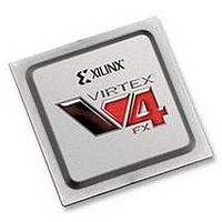
XC4VFX60-10FFG1152C Xilinx Inc, XC4VFX60-10FFG1152C Datasheet - Page 68

XC4VFX60-10FFG1152C
Manufacturer Part Number
XC4VFX60-10FFG1152C
Description
IC FPGA VIRTEX-4 FX 60K 1152FBGA
Manufacturer
Xilinx Inc
Series
Virtex™-4r
Datasheets
1.XC4VFX12-10FFG668C.pdf
(58 pages)
2.XC4VFX12-10FFG668C.pdf
(9 pages)
3.XC4VFX12-10FFG668C.pdf
(406 pages)
Specifications of XC4VFX60-10FFG1152C
Total Ram Bits
4276224
Number Of Logic Elements/cells
56880
Number Of Labs/clbs
6320
Number Of I /o
576
Voltage - Supply
1.14 V ~ 1.26 V
Mounting Type
Surface Mount
Operating Temperature
0°C ~ 85°C
Package / Case
1152-BBGA, FCBGA
No. Of Logic Blocks
6656
No. Of Macrocells
56880
Family Type
Virtex-4
No. Of Speed Grades
10
No. Of I/o's
576
Clock Management
DCM
Core Supply
RoHS Compliant
Package
1152FCBGA
Family Name
Virtex®-4
Device Logic Units
56880
Typical Operating Supply Voltage
1.2 V
Maximum Number Of User I/os
576
Ram Bits
4276224
Lead Free Status / RoHS Status
Lead free / RoHS Compliant
For Use With
HW-V4-ML410-UNI-G - EVALUATION PLATFORM VIRTEX-4
Number Of Gates
-
Lead Free Status / RoHS Status
Lead free / RoHS Compliant
Available stocks
Company
Part Number
Manufacturer
Quantity
Price
Company:
Part Number:
XC4VFX60-10FFG1152C
Manufacturer:
XilinxInc
Quantity:
3 000
Company:
Part Number:
XC4VFX60-10FFG1152C
Manufacturer:
Xilinx Inc
Quantity:
10 000
- XC4VFX12-10FFG668C PDF datasheet
- XC4VFX12-10FFG668C PDF datasheet #2
- XC4VFX12-10FFG668C PDF datasheet #3
- Current page: 68 of 406
- Download datasheet (6Mb)
Chapter 2: Digital Clock Managers (DCMs)
68
CLKOUT_PHASE_SHIFT Attribute
DCM_AUTOCALIBRATION Attribute
DCM_PERFORMANCE_MODE Attribute
The CLKOUT_PHASE_SHIFT attribute indicates the mode of the phase shift applied to the
DCM outputs. The possible values are NONE, FIXED, VARIABLE_POSITIVE,
VARIABLE_CENTER, or DIRECT. The default value is NONE.
When set to NONE, a phase shift cannot be performed and a phase-shift value has no effect
on the DCM outputs. When set to FIXED, the DCM outputs are phase-shifted by a fixed
phase from the CLKIN. The phase-shift value is determined by the PHASE_SHIFT
attribute. If the CLKOUT_PHASE_SHIFT attribute is set to FIXED or NONE, then the
PSEN, PSINCDEC, and the PSCLK inputs must be tied to ground.
When set to VARIABLE_POSITIVE, the DCM outputs can be phase-shifted in variable
mode in the positive range with respect to CLKIN. When set to VARIABLE_CENTER, the
DCM outputs can be phase-shifted in variable mode, in the positive and negative range
with respect to CLKIN. If set to VARIABLE_POSITIVE or VARIABLE_CENTER, each
phase-shift increment (or decrement) will increase (or decrease) the phase shift by a period
of 1/256 x CLKIN period.
When set to DIRECT, the DCM output can be phase-shifted in variable mode in the
positive range with respect to CLKIN. Each phase-shift increment/decrement will
increase/decrease the phase shift by one DCM_TAP (see the
The starting phase in the VARIABLE_POSITIVE and VARIABLE_CENTER modes is
determined by the phase-shift value. The starting phase in the DIRECT mode is always
zero, regardless of the value specified by the PHASE_SHIFT attribute. Thus, the
PHASE_SHIFT attribute should be set to zero when DIRECT mode is used. A non-zero
phase-shift value for DIRECT mode can be loaded to the DCM using Dynamic
Reconfiguration Ports in the
The autocalibration block protects the DCM from the effects of negative bias temperature
instability (NBTI). This attribute cannot be set to FALSE unless the user guarantees that
CLKIN and CLKFB (if external feedback is used) never stop. The macro can also be
disabled if the user can guarantee that DCM is held in reset when the clocks are stopped. If
this attribute is set to FALSE, the reset requirement is three clock cycles.
The DCM_PERFORMANCE_MODE attribute allows the choice of optimizing the DCM
either for high frequency and low jitter or for low frequency and a wide phase-shift range.
The attribute values are MAX_SPEED and MAX_RANGE. The default value is
MAX_SPEED. When set to MAX_SPEED, the DCM is optimized to produce high
frequency clocks with low jitter. However, the phase-shift range is smaller than when
MAX_RANGE is selected. When set to MAX_RANGE, the DCM is optimized to produce
low frequency clocks with a wider phase-shift range. The DCM_PERFORMANCE_MODE
affects the following specifications: DCM input and output frequency range, phase-shift
range, output jitter, DCM_TAP, CLKIN_CLKFB_PHASE, CLKOUT_PHASE, and duty-
cycle precision. The
For most cases, the DCM_PERFORMANCE_MODE attribute should be set to
MAX_SPEED (default). Consider changing to MAX_RANGE only in these situations:
•
•
The frequency needs to be below the low frequency limit of the MAX_SPEED setting.
A greater absolute phase-shift range is required.
Virtex-4 Data Sheet
www.xilinx.com
Virtex-4 Configuration
specifies these values.
Guide.
UG070 (v2.6) December 1, 2008
Virtex-4 Data
Virtex-4 FPGA User Guide
Sheet).
R
Related parts for XC4VFX60-10FFG1152C
Image
Part Number
Description
Manufacturer
Datasheet
Request
R

Part Number:
Description:
IC FPGA VIRTEX-4 FX 60K 672-FBGA
Manufacturer:
Xilinx Inc

Part Number:
Description:
IC FPGA VIRTEX-4 FX 60K 672-FBGA
Manufacturer:
Xilinx Inc
Datasheet:

Part Number:
Description:
IC FPGA VIRTEX-4 FX 60K 672-FBGA
Manufacturer:
Xilinx Inc
Datasheet:

Part Number:
Description:
IC FPGA VIRTEX-4 FX 60K 1152FBGA
Manufacturer:
Xilinx Inc
Datasheet:

Part Number:
Description:
IC FPGA VIRTEX-4 FX 60K 1152FBGA
Manufacturer:
Xilinx Inc
Datasheet:

Part Number:
Description:
IC FPGA VIRTEX-4FX 1152FFBGA
Manufacturer:
Xilinx Inc
Datasheet:

Part Number:
Description:
IC FPGA VIRTEX-4FX 1152FFBGA
Manufacturer:
Xilinx Inc
Datasheet:

Part Number:
Description:
FPGA Virtex®-4 Family 56880 Cells 90nm (CMOS) Technology 1.2V 672-Pin FCBGA
Manufacturer:
Xilinx Inc
Datasheet:

Part Number:
Description:
IC FPGA VIRTEX-4 FX 60K 672-FBGA
Manufacturer:
Xilinx Inc
Datasheet:

Part Number:
Description:
IC FPGA VIRTEX-4 FX 60K 672-FBGA
Manufacturer:
Xilinx Inc
Datasheet:

Part Number:
Description:
IC FPGA VIRTEX-4 FX 60K 1152FBGA
Manufacturer:
Xilinx Inc
Datasheet:

Part Number:
Description:
FPGA Virtex®-4 Family 56880 Cells 90nm (CMOS) Technology 1.2V 672-Pin FCBGA
Manufacturer:
Xilinx Inc
Datasheet:

Part Number:
Description:
IC CPLD .8K 36MCELL 44-VQFP
Manufacturer:
Xilinx Inc
Datasheet:

Part Number:
Description:
IC CPLD 72MCRCELL 10NS 44VQFP
Manufacturer:
Xilinx Inc
Datasheet:


