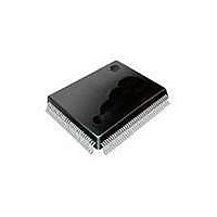
SAA7115HLBE NXP Semiconductors, SAA7115HLBE Datasheet - Page 52

SAA7115HLBE
Manufacturer Part Number
SAA7115HLBE
Description
Video ICs ADV DGTL VIDEO DECODR
Manufacturer
NXP Semiconductors
Datasheet
1.SAA7115HLBE.pdf
(548 pages)
Specifications of SAA7115HLBE
Operating Supply Voltage
3.3 V
Maximum Operating Temperature
+ 70 C
Package / Case
SOT-407
Minimum Operating Temperature
0 C
Mounting Style
SMD/SMT
Number Of Channels
2
Resolution
8 bit
Lead Free Status / RoHS Status
Lead free / RoHS Compliant
Other names
SAA7115HL/V1,557 SAF7115HLBE
- Current page: 52 of 548
- Download datasheet (6Mb)
PNX1300/01/02/11 Data Book
• A high-performance bus and memory system that
• A flexible external bus interface.
Figure 2-1
a PNX1300 system consists of the PNX1300 micropro-
cessor itself, external synchronous DRAM (SDRAM),
and the external circuitry needed to interface to incoming
and/or outgoing video and audio data streams and com-
munication lines. PNX1300’s external peripheral bus can
gluelessly interface to PC! 2.1 components and/or 8-bit
microprocessor peripherals.
Figure 2-2
PNX1300 system. A video input stream might come di-
rectly from a CCIR 656-compliant video camera chip in
YUV 4:2:2 format through a glueless interface in this
case. An analog camera can be connected via a CCIR
656 interface chip (such as the Philips SAA7113H).
PNX1300 outputs a CCIR656 video stream to drive a
dedicated video monitor. Stereo audio input and up to 8-
channel audio output require only low-cost external ADC
and DAC. The operation of the video and audio interface
units is highly customizable through programmable pa-
rameters.
Figure 2-1. PNX1300 block diagram.
2-2
provide communication between PNX1300’s pro-
cessing units.
I
2
I
shows a PNX1300 block diagram. The bulk of
S DC, up to 22 MHz AO_SCK
2
S DC, up to 22 MHz AI_SCK
shows a possible minimally configured
up to 81 MHz (40 Mpix/sec)
2/4/6/8 ch. digital audio
CCIR656 dig. video
Stereo digital audio
16 and 32-bit data
up to 40 Mbit/sec
8 and 16-bit data
PRELIMINARY SPECIFICATION
camera, etc.
YUV 4:2:2
I
2
C bus to
IEC958
PNX1300
I
VLIW
SPDIF Out
2
Audio Out
CPU
C Interface
Audio In
Video In
32K
16K
D$
PCI-XIO Interface
I$
Main Memory
Interface
SDRAM
Figure 2-2. PNX1300 system connections. A minimal
PNX1300 requires few supporting components.
The glueless PCI interface allows the PNX1300 to dis-
play video in a host PC’s video card. The Image Copro-
cessor (ICP) provides display support for live video input
an arbitrary number of arbitrarily overlapped windows.
audio in
Synchronous
Coprocessor
Coprocessor
stereo
Video Out
digital video
Interface
Timers
DVDD
Serial
Image
CCIR656
VLD
P C I a n d 8 - b it p e r i p h e r a l b u s
32-bit data
up to 572 MB/sec
R O M
JTAG
ADC
PNX1300
2Mx32 SDRAM
Huffman decoder
Slice-at-a-time
MPEG-1 & 2
Down & up scaling
YUV → RGB
50 Mpix/sec
External bus
- PC!2.1 (32 bits, 33-MHz)
+ glueless 24A/8D slaves
CCIR656 digital video
YUV 4:2:2
up to 81 MHz (40 Mpix/sec)
Analog modem or ISDN
front end
Philips Semiconductors
CCIR656
dig. video
modem
front end
DAC
audio out
2 - 8 ch
Related parts for SAA7115HLBE
Image
Part Number
Description
Manufacturer
Datasheet
Request
R
Part Number:
Description:
Ntsc/pal/secam 9-bit Video Decoder
Manufacturer:
NXP Semiconductors
Datasheet:
Part Number:
Description:
NXP Semiconductors designed the LPC2420/2460 microcontroller around a 16-bit/32-bitARM7TDMI-S CPU core with real-time debug interfaces that include both JTAG andembedded trace
Manufacturer:
NXP Semiconductors
Datasheet:

Part Number:
Description:
NXP Semiconductors designed the LPC2458 microcontroller around a 16-bit/32-bitARM7TDMI-S CPU core with real-time debug interfaces that include both JTAG andembedded trace
Manufacturer:
NXP Semiconductors
Datasheet:
Part Number:
Description:
NXP Semiconductors designed the LPC2468 microcontroller around a 16-bit/32-bitARM7TDMI-S CPU core with real-time debug interfaces that include both JTAG andembedded trace
Manufacturer:
NXP Semiconductors
Datasheet:
Part Number:
Description:
NXP Semiconductors designed the LPC2470 microcontroller, powered by theARM7TDMI-S core, to be a highly integrated microcontroller for a wide range ofapplications that require advanced communications and high quality graphic displays
Manufacturer:
NXP Semiconductors
Datasheet:
Part Number:
Description:
NXP Semiconductors designed the LPC2478 microcontroller, powered by theARM7TDMI-S core, to be a highly integrated microcontroller for a wide range ofapplications that require advanced communications and high quality graphic displays
Manufacturer:
NXP Semiconductors
Datasheet:
Part Number:
Description:
The Philips Semiconductors XA (eXtended Architecture) family of 16-bit single-chip microcontrollers is powerful enough to easily handle the requirements of high performance embedded applications, yet inexpensive enough to compete in the market for hi
Manufacturer:
NXP Semiconductors
Datasheet:
Part Number:
Description:
The XA-S3 device is a member of Philips Semiconductors? XA(eXtended Architecture) family of high performance 16-bitsingle-chip microcontrollers
Manufacturer:
NXP Semiconductors
Datasheet:

Part Number:
Description:
The NXP BlueStreak LH75401/LH75411 family consists of two low-cost 16/32-bit System-on-Chip (SoC) devices
Manufacturer:
NXP Semiconductors
Datasheet:

Part Number:
Description:
The NXP LPC3130/3131 combine an 180 MHz ARM926EJ-S CPU core, high-speed USB2
Manufacturer:
NXP Semiconductors
Datasheet:

Part Number:
Description:
The NXP LPC3141 combine a 270 MHz ARM926EJ-S CPU core, High-speed USB 2
Manufacturer:
NXP Semiconductors

Part Number:
Description:
The NXP LPC3143 combine a 270 MHz ARM926EJ-S CPU core, High-speed USB 2
Manufacturer:
NXP Semiconductors

Part Number:
Description:
The NXP LPC3152 combines an 180 MHz ARM926EJ-S CPU core, High-speed USB 2
Manufacturer:
NXP Semiconductors

Part Number:
Description:
The NXP LPC3154 combines an 180 MHz ARM926EJ-S CPU core, High-speed USB 2
Manufacturer:
NXP Semiconductors


