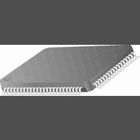
CR16MCS9VJE8 National Semiconductor, CR16MCS9VJE8 Datasheet - Page 92

CR16MCS9VJE8
Manufacturer Part Number
CR16MCS9VJE8
Description
16-Bit Microcontroller IC
Manufacturer
National Semiconductor
Datasheet
1.CR16MCS9VJE8.pdf
(156 pages)
Specifications of CR16MCS9VJE8
Controller Family/series
CR16X
Core Size
16 Bit
Program Memory Size
64K X 8 Flash
Digital Ic Case Style
PQFP
No. Of Pins
80
Mounting Type
Surface Mount
Clock Frequency
25MHz
Lead Free Status / RoHS Status
Contains lead / RoHS non-compliant
Available stocks
Company
Part Number
Manufacturer
Quantity
Price
Company:
Part Number:
CR16MCS9VJE8
Manufacturer:
ON
Quantity:
8 917
Company:
Part Number:
CR16MCS9VJE8-CBB
Manufacturer:
ON
Quantity:
846
Company:
Part Number:
CR16MCS9VJE8-CBC
Manufacturer:
ON
Quantity:
109
Company:
Part Number:
CR16MCS9VJE8-CBD
Manufacturer:
ON
Quantity:
17
Company:
Part Number:
CR16MCS9VJE8-CBE
Manufacturer:
ON
Quantity:
1 950
www.national.com
Interframe Space
Data and remote frames are separated from every preceding
frame (data, remote, error and overload frames) by the inter-
frame space (see Figure50). Error and overload frames are
20.2.2
There are multiple mechanisms in the CAN protocol to detect
errors and inhibit erroneous modules from disabling all bus
activities. Each CAN module includes two error counters, a
receive and a transmit error counter, for error management.
Error Types
The following errors can be detected:
— Bit Error
A CAN device which is currently transmitting also mon-
itors the bus. If the monitored bit value is different from
the transmitted bit value, a bit error is detected. How-
ever, the reception of a ‘dominant’ bit instead of a ‘re-
cessive’ bit during the transmission of a passive error
flag, during the stuffed bit stream of the arbitration field
or during the acknowledge slot is not interpreted as a
bit error.
Error Detection and Management
INT = Intermission
Suspend Transmission is only for error passive nodes.
ANY FRAME
r
ACTIVE
ERROR
SYNC
r
r r r
11 consecutive ‘recessive’ bits
11 consecutive ‘recessive’ bits
128 occurrences of
received
r
(TEC OR REC) > 95
(TEC AND REC) < 96
r
r r r r
INT
3
Figure 51. CR16CAN Bus States
Figure 50.
r r
INTERFRAME SPACE
external RESET or
enable CR16CAN
TRANSMIT
SUSPEND
r
8
r r r r
WARNING
ERROR
CAN Interframe Space
92
r
not preceded by an interframe space; they can be transmit-
ted as soon as the condition occurs. The interframe space
consists of a minimum of three bit fields depending on the er-
ror state of the node.
r
BUS IDLE
— Stuff Error
— Form Error
— Bit CRC Error
— Acknowledgment Error
(TEC AND REC) < 128
(TEC OR REC) > 127
A stuff error is detected if the bit level after 6 consecu-
tive bit times has not changed in a message field that
has to be coded according to the bit stuffing method.
A form error is detected, if a fixed frame bit (e.g., CRC
delimiter, ACK delimiter) does not have the specified
value. For a receiver, a ‘dominant’ bit during the last bit
of End of Frame does not constitute a frame error.
A CRC error is detected if the remainder of the CRC
calculation of a received CRC polynomial is non-zero.
An acknowledgment error is detected whenever a
transmitting node does not get an acknowledgment
from any other node (i.e., when the transmitter does
not receive a ‘dominant’ bit during the ACK frame)
r
r
r
d
TEC > 255
DATA FRAME OR
REMOTE FRAME
ERROR
PASSIVE
OFF
BUS
Note:
d = dominant
r = recessive


