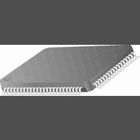
CR16MCS9VJE8 National Semiconductor, CR16MCS9VJE8 Datasheet - Page 45

CR16MCS9VJE8
Manufacturer Part Number
CR16MCS9VJE8
Description
16-Bit Microcontroller IC
Manufacturer
National Semiconductor
Datasheet
1.CR16MCS9VJE8.pdf
(156 pages)
Specifications of CR16MCS9VJE8
Controller Family/series
CR16X
Core Size
16 Bit
Program Memory Size
64K X 8 Flash
Digital Ic Case Style
PQFP
No. Of Pins
80
Mounting Type
Surface Mount
Clock Frequency
25MHz
Lead Free Status / RoHS Status
Contains lead / RoHS non-compliant
Available stocks
Company
Part Number
Manufacturer
Quantity
Price
Company:
Part Number:
CR16MCS9VJE8
Manufacturer:
ON
Quantity:
8 917
Company:
Part Number:
CR16MCS9VJE8-CBB
Manufacturer:
ON
Quantity:
846
Company:
Part Number:
CR16MCS9VJE8-CBC
Manufacturer:
ON
Quantity:
109
Company:
Part Number:
CR16MCS9VJE8-CBD
Manufacturer:
ON
Quantity:
17
Company:
Part Number:
CR16MCS9VJE8-CBE
Manufacturer:
ON
Quantity:
1 950
14.0 Real-Time Timer and WATCHDOG
The Timing and WATCHDOG Module (TWM) generates the
clocks and interrupts used for timing periodic functions in the
system, and also provides Watchdog protection against soft-
ware errors. The module operates off the slow clock either
generated by the external 32kHz oscillator or from the pres-
caled high speed system clock. The maximum operating
clock frequency is 100kHz.
The WATCHDOG is designed to detect program execution
errors. Once WATCHDOG operation is initiated, the software
must periodically write a specific value to a WATCHDOG reg-
ister. If the software fails to do so, a WATCHDOG error is trig-
gered, which resets the device.
The TWM is flexible in allowing selection of a variety of clock
ratios and clock sources for the WATCHDOG circuit. Once
the software configures the TWM, it can lock the configura-
tion for a higher level of protection against erroneous soft-
ware action. Once locked, the TWM can be released only by
a device reset.
14.1
Figure10 is a block diagram showing the internal structure of
the Timing and WATCHDOG module. There are two main
sections: the Real-Time Timer (T0) section at the top and the
WATCHDOG section on the bottom.
CLKIN1
slow clock from
dual clock and
reset module
TWM STRUCTURE
REAL TIME TIMER (T0)
WATCHDOG
T0IN
Figure 10. Timing and WATCHDOG Module Block Diagram
5-bit pre-scaler counter
WATCHDOG Timer
TWMT0 register
WATCHDOG
16-bit Timer (Timer0)
Restart
Service
Logic
(TWCP)
45
WATCHDOG ERROR
Restart
All counting activities of the module are based on the slow
clock (SLCLK). A prescaler counter divides this clock to
make a slower clock. The prescaler factor is defined by a 3-
bit field in the Timer and WATCHDOG Prescaler register,
which selects either 1, 2, 4, 8, 16, or 32 and the divide-by fac-
tor. Thus, the prescaled clock period can be set to 1, 2, 4, 8,
16, or 32 times the slow clock period. The prescaled clock
signal is called T0IN.
14.2
Timer T0 is a programmable 16-bit down counter that can be
used as the time base for real-time operations such as a pe-
riodic audible tick. It can also be used to drive the WATCH-
DOG circuit.
The timer starts counting from the value loaded into the
TWMT0 register and counts down on each rising edge of
T0IN. When the timer reaches zero, it is automatically reload-
ed from the TWMT0 register and continues counting down
from that value. Thus, the frequency of the timer is:
When an external crystal oscillator is used as the SLCLK
source or when the fast clock is divided accordingly, f SLCLK
is 32.768 kHz.
The value stored in TWMT0 can range from 0001 hex to
FFFF hex.
f SLCLK / [(TWMT0+1) * prescaler]
Underflow
TIMER T0 OPERATION
T0CSR Contrl. Reg.
WDSDM
WDCNT
Peripheral Bus
Underflow
WDERR
T0OUT
(to Multi-Input-
T0LINT
(to ICU)
Wake-Up)
www.national.com


