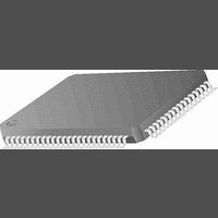
CR16MCS9VJE8 National Semiconductor, CR16MCS9VJE8 Datasheet - Page 63

CR16MCS9VJE8
Manufacturer Part Number
CR16MCS9VJE8
Description
16-Bit Microcontroller IC
Manufacturer
National Semiconductor
Datasheet
1.CR16MCS9VJE8.pdf
(156 pages)
Specifications of CR16MCS9VJE8
Controller Family/series
CR16X
Core Size
16 Bit
Program Memory Size
64K X 8 Flash
Digital Ic Case Style
PQFP
No. Of Pins
80
Mounting Type
Surface Mount
Clock Frequency
25MHz
Lead Free Status / RoHS Status
Contains lead / RoHS non-compliant
Available stocks
Company
Part Number
Manufacturer
Quantity
Price
Company:
Part Number:
CR16MCS9VJE8
Manufacturer:
ON
Quantity:
8 917
Company:
Part Number:
CR16MCS9VJE8-CBB
Manufacturer:
ON
Quantity:
846
Company:
Part Number:
CR16MCS9VJE8-CBC
Manufacturer:
ON
Quantity:
109
Company:
Part Number:
CR16MCS9VJE8-CBD
Manufacturer:
ON
Quantity:
17
Company:
Part Number:
CR16MCS9VJE8-CBE
Manufacturer:
ON
Quantity:
1 950
IxBEN
IxCEN
IxDEN
16.2.5
The Interrupt Pending (INTPND) register is a word-wide
read/write register which contains all 16 interrupt pending
flags. There are four interrupt pending flags called IxAPD
through IxDPD per timer subsystem. Each interrupt pending
flag is set by a hardware event and can be cleared if the user
software writes a 1 to the bit position. The value will remain
unchanged if a 0 is written to the bit position. All interrupt
pending flags are cleared (0) upon reset.
IxAPD
IxBPD
I4DPD I4CPD I4BPD I4APD I3DPD I3CPD I3BPD I3APD
I2DPD I2CPD I2BPD I2APD I1DPD I1CPD I1BPD I1APD
15
7
Interrupt Pending Register (INTPND)
14
6
flag will be updated regardless of the value of
the IxAEN bit.
0
1
Timer x interrupt B enable. Enable/Disable an
interrupt request based on the corresponding
IxBPD flag being set. The associated IxBPD
flag will be updated regardless of the value of
the IxBEN bit.
0
1
Timer x interrupt C enable. Enable/Disable an
interrupt request based on the corresponding
IxCPD flag being set. The associated IxCPD
flag will be updated regardless of the value of
the IxCEN bit.
0
1
Timer x interrupt D enable. Enable/Disable an
interrupt request based on the corresponding
IxDPD flag being set. The associated IxDPD
flag will be updated regardless of the value of
the IxDEN bit.
0
1
Timer x interrupt A pending. If set (1), indicates
that an interrupt condition for the related timer
subsystem has occurred. Table 17 on page 61
lists the hardware condition which causes this
bit to be set.
Timer x interrupt B pending. If set (1), indicates
that an interrupt condition for the related timer
13
5
Enable system interrupt request for the
IxAPD pending flag
Disable system interrupt request for the
IxAPD pending flag
Enable system interrupt request for the
IxBPD pending flag
Disable system interrupt request for the
IxBPD pending flag
Enable system interrupt request for the
IxCPD pending flag
Disable system interrupt request for the
IxCPD pending flag
Enable system interrupt request for the
IxDPD pending flag
Disable system interrupt request for the
IxDPD pending flag
12
4
11
3
10
2
9
1
8
0
63
IxCPD
IxDPD
16.2.6
CLK1PS is a word-wide read/write register. The register is
split into two 8-bit wide field called C1PRSC and C2PRSC.
Each field holds the 8-bit clock prescaler compare value for
timer subsystems 1 and 2 respectively. The register is
cleared upon reset.
C1PRSC
C2PRSC
16.2.7
The Clock Prescaler Register 2 (CLK2PS) is a word-wide
read/write register. The register is split into two 8-bit wide
fields called C3PRSC and C4PRSC. Each field holds the 8-
bit clock prescaler compare value for timer subsystems 3 and
4 respectively. The register is cleared upon reset.
C3PRSC
C4PRSC
16.2.8
The Counter (COUNTx) registers are word wide read/write
registers. There are a total of four registers called COUNT1
through COUNT4, one for each of the four timer subsystems.
The user software may read the registers at any time. Read-
15
15
Clock Prescaler Register 1 (CLK1PS)
Clock Prescaler Register 2 (CLK2PS)
Counter Registers (COUNTx)
C2PRSC
C4PRSC
subsystem has occurred. Table 17 on page 61
lists the hardware condition which causes this
bit to be set.
Timer x interrupt C pending. If set (1), indicates
that an interrupt condition for the related timer
subsystem has occurred. Table 17 on page 61
lists the hardware condition which causes this
bit to be set.
Timer x interrupt D pending. If set (1), indicates
that an interrupt condition for the related timer
subsystem has occurred. Table 17 on page 61
lists the hardware condition which causes this
bit to be set.
Clock Prescaler 1 compare value. Holds the 8-
bit prescaler value for timer subsystem 1. The
counter of timer subsystem is incremented
each time when the clock prescaler compare
value matches the value of the clock prescaler
counter. The divide-by-ratio is equal to
C1PRSC+1 i.e. a value of 00
vide by 1 whereas the maximum divide-by ratio
is 256 for a C1PRSC value of FF
Clock Prescaler 2 compare value. Holds the 8-
bit prescaler value for timer subsystem 2. The
functionality of this field is identical to the one
described for C1PRSC in the previous para-
graph.
Clock Prescaler 3 compare value. Holds the 8-
bit prescaler value for timer subsystem 3. The
functionality of this field is identical to the one
described for C1PRSC on page 63.
Clock Prescaler 4 compare value. Holds the 8-
bit prescaler value for timer subsystem 4. The
functionality of this field is identical to the one
described for C1PRSC on page 63.
8 7
8 7
C3PRSC
C1PRSC
www.national.com
1 6
results in a di-
1 6
.
0
0


