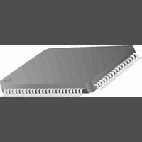
CR16MCS9VJE8 National Semiconductor, CR16MCS9VJE8 Datasheet - Page 77

CR16MCS9VJE8
Manufacturer Part Number
CR16MCS9VJE8
Description
16-Bit Microcontroller IC
Manufacturer
National Semiconductor
Datasheet
1.CR16MCS9VJE8.pdf
(156 pages)
Specifications of CR16MCS9VJE8
Controller Family/series
CR16X
Core Size
16 Bit
Program Memory Size
64K X 8 Flash
Digital Ic Case Style
PQFP
No. Of Pins
80
Mounting Type
Surface Mount
Clock Frequency
25MHz
Lead Free Status / RoHS Status
Contains lead / RoHS non-compliant
Available stocks
Company
Part Number
Manufacturer
Quantity
Price
Company:
Part Number:
CR16MCS9VJE8
Manufacturer:
ON
Quantity:
8 917
Company:
Part Number:
CR16MCS9VJE8-CBB
Manufacturer:
ON
Quantity:
846
Company:
Part Number:
CR16MCS9VJE8-CBC
Manufacturer:
ON
Quantity:
109
Company:
Part Number:
CR16MCS9VJE8-CBD
Manufacturer:
ON
Quantity:
17
Company:
Part Number:
CR16MCS9VJE8-CBE
Manufacturer:
ON
Quantity:
1 950
UnETI
UnERI
UnEEI
18.4
The USART baud rate is determined by the system clock fre-
quency and the values programmed into the UnPSR and Un-
BAUD registers. Unless the system clock frequency is an
exact multiple of the desired baud rate, there will be a small
amount of error in the resulting baud rate clock.
The method of baud rate calculation depends on whether the
USART is configured to operate in the asynchronous or syn-
chronous mode.
18.4.1
The equation for calculating the baud rate in asynchronous
mode is:
where BR is the baud rate, SYS_CLK is the system clock, N
is the value of the baud rate divisor + 1, and P is the prescaler
divide factor selected by the value in the UnPSR register.
Assuming a system clock of 5 MHz and a desired baud rate
of 9600, the NxP term according to the equation above is:
The NxP term is then divided by each Prescaler Factor from
Table 19 to obtain a value closest to an integer. The factor for
this example is 6.5.
The baud rate register is programmed with a baud rate divi-
sor of 4 (N = baud rate divisor +1). This produces a baud
clock of:
Note that the percent error is much lower than would be pos-
sible without the non-integer prescaler factor. Refer to the ta-
ble below for more examples.
System
10 MHz
4 MHz
5 MHz
Clock
Baud Rate in Asynchronous Mode
BAUD RATE CALCULATIONS
%error
Baud Rate
Enable Transmitter Interrupt. This read/write
bit, when set to 1, enables generation of an in-
terrupt when the hardware sets the UnTBE bit.
Enable Receiver Interrupt. This read/write bit,
when set to 1, enables generation of an inter-
rupt when the hardware sets the UnRBF bit.
Enable Receive Error Interrupt. This read/write
bit, when set to 1, enables generation of an in-
terrupt when the hardware sets the UnERR bit
in the UnSTAT register.
BR
Desired
N
19200
N
9600
9600
=
=
P
=
BR
32.552
----------------
---------------------------------
=
16 5 6.5
6.5
---------------------------------------------
-----------------------------
9615.385 9600
5
=
16 9600
N P
2 13
5 6.5
5 6.5
5
10
-------------------------------
16
=
SYS_CLK
10
6
9600
5.008 (N = 5)
6
N P
–
=
Baud Rate
19230.769
9615.385
9615.385
=
9615.385
Actual
32.552
=
0.16
Percent
Error
0.16
0.16
0.16
77
18.4.2
The equation for calculating the baud rate in synchronous
mode is:
where BR is the baud rate, SYS_CLK is the system clock, N
is the value of the baud rate divisor + 1, and P is the prescaler
divide factor selected by the value in the UnPSR register.
Use the same procedure to determine the values of N and P
as in the asynchronous mode. In this case, however, only in-
teger prescaler values are allowed.
System
20 MHz
Clock
Baud Rate in Synchronous Mode
Baud Rate
Desired
19200
BR
=
N P
5 13
----------------------------
SYS_CLK
2
N P
Baud Rate
19230.769
Actual
www.national.com
Percent
Error
0.16


