MCIMX53-START Freescale Semiconductor, MCIMX53-START Datasheet - Page 26
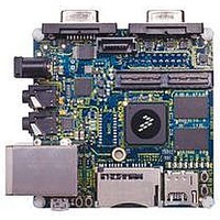
MCIMX53-START
Manufacturer Part Number
MCIMX53-START
Description
KIT DEVELOPMENT I.MX53
Manufacturer
Freescale Semiconductor
Series
i.MX53r
Type
MCUr
Datasheets
1.MCIMX53-START.pdf
(2 pages)
2.MCIMX53-START.pdf
(180 pages)
3.MCIMX53-START.pdf
(204 pages)
Specifications of MCIMX53-START
Contents
Board
Silicon Manufacturer
Freescale
Core Architecture
ARM
Core Sub-architecture
Cortex - A8
Silicon Core Number
I.MX5
Silicon Family Name
I.MX53
Peak Reflow Compatible (260 C)
Yes
Rohs Compliant
Yes
Leaded Process Compatible
Yes
Lead Free Status / RoHS Status
Lead free / RoHS Compliant
For Use With/related Products
i.MX53
Lead Free Status / Rohs Status
Supplier Unconfirmed
Available stocks
Company
Part Number
Manufacturer
Quantity
Price


Electrical Characteristics
Figure 2
1. If fuse writing is required, VDD_FUSE should be powered ON after NVCC_CKIH is stable.
26
NVCC_SRTC_POW
(should remain ON)
VCC
NVCC_CKIH
IO Supplies below or equal to
2.8 V nom./3.1 V max.
(in any order, after NVCC_CKIH
IO Supplies above 2.8 V nom./3.1 V max
(in any order, if needed)
VDD_REG
NVCC_EMI_DRAM
POR_B pin released
by Power Management IC
ramp up start, if needed)
VDDA,VDDAL1,VDDGP
(in any order)
VP, VPH
(in any order)
shows the power-up sequence diagram.
Need to ensure that there is no back voltage (leakage) from any supply on
the board towards the 3.3 V supply (for example, from the parts that use
both 1.8 V and the 3.3 V supply).
i.MX53xD Applications Processors for Consumer Products, Rev. 1
Figure 2. Power Up Detailed Sequence
Δt > 0
Δt > 0
90%
90%
Δt > 0
NOTE
90%
90%
Δt > 0
Δt > 0
90%
90%
Δt > 0
90%
1
Δt > 0
Δt > 0
90%
90%
Δt > 0
Freescale Semiconductor
Related parts for MCIMX53-START
Image
Part Number
Description
Manufacturer
Datasheet
Request
R

Part Number:
Description:
MCIMX-LVDS1
Manufacturer:
Freescale Semiconductor
Datasheet:

Part Number:
Description:
Manufacturer:
Freescale Semiconductor, Inc
Datasheet:
Part Number:
Description:
Manufacturer:
Freescale Semiconductor, Inc
Datasheet:
Part Number:
Description:
Manufacturer:
Freescale Semiconductor, Inc
Datasheet:
Part Number:
Description:
Manufacturer:
Freescale Semiconductor, Inc
Datasheet:
Part Number:
Description:
Manufacturer:
Freescale Semiconductor, Inc
Datasheet:
Part Number:
Description:
Manufacturer:
Freescale Semiconductor, Inc
Datasheet:
Part Number:
Description:
Manufacturer:
Freescale Semiconductor, Inc
Datasheet:
Part Number:
Description:
Manufacturer:
Freescale Semiconductor, Inc
Datasheet:
Part Number:
Description:
Manufacturer:
Freescale Semiconductor, Inc
Datasheet:
Part Number:
Description:
Manufacturer:
Freescale Semiconductor, Inc
Datasheet:
Part Number:
Description:
Manufacturer:
Freescale Semiconductor, Inc
Datasheet:
Part Number:
Description:
Manufacturer:
Freescale Semiconductor, Inc
Datasheet:
Part Number:
Description:
Manufacturer:
Freescale Semiconductor, Inc
Datasheet:
Part Number:
Description:
Manufacturer:
Freescale Semiconductor, Inc
Datasheet: