MCIMX53-START Freescale Semiconductor, MCIMX53-START Datasheet - Page 147
MCIMX53-START
Manufacturer Part Number
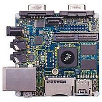
MCIMX53-START
Description
KIT DEVELOPMENT I.MX53
Manufacturer
Freescale Semiconductor
Series
i.MX53r
Type
MCUr
Datasheets
1.MCIMX53-START.pdf
(2 pages)
2.MCIMX53-START.pdf
(180 pages)
3.MCIMX53-START.pdf
(204 pages)
Specifications of MCIMX53-START
Contents
Board
Silicon Manufacturer
Freescale
Core Architecture
ARM
Core Sub-architecture
Cortex - A8
Silicon Core Number
I.MX5
Silicon Family Name
I.MX53
Peak Reflow Compatible (260 C)
Yes
Rohs Compliant
Yes
Leaded Process Compatible
Yes
Lead Free Status / RoHS Status
Lead free / RoHS Compliant
For Use With/related Products
i.MX53
Lead Free Status / Rohs Status
Supplier Unconfirmed
Available stocks
Company
Part Number
Manufacturer
Quantity
Price


4.7.18.2 Parallel Interface (Normal ULPI) Timing
Electrical and timing specifications of Parallel Interface (Normal ULPI) for Host Port2 and Port3 are
presented in the subsequent sections.
4.7.19
This section describes the USB-OTG PHY and the USB Host port PHY parameters.
4.7.19.1 USB PHY AC Parameters
Table 99
Freescale Semiconductor
US15
US16
US17
USB_Clk
USB_Data[7:0]
USB_Dir
USB_Stp
USB_Nxt
ID
lists the AC timing parameters for USB PHY.
USB_Stp
USB_Data
USB_Clk
USB_Dir/Nxt
USB PHY Parameters
Name
Output delay Time(Stp out, Data out
Table 97. Signal Definitions - Parallel Interface (Normal ULPI)
Figure 99. USB Transmit/Receive Waveform in Parallel Mode
i.MX53xD Applications Processors for Consumer Products, Rev. 1
Setup Time(Dir&Nxt in, Data in)
Table 98. USB Timing Specification for Normal ULPI mode
Hold Time(Dir&Nxt in, Data in)
US15
US15
Parameter
Direction
Out
I/O
In
In
In
US16
US16
Interface clock. All interface signals are synchronous to Clock.
Bi-directional data bus, driven low by the link during idle. Bus
ownership is determined by Dir.
Direction. Control the direction of the Data bus.
Stop. The link asserts this signal for 1 clock cycle to stop the
data stream currently on the bus.
Next. The PHY asserts this signal to throttle the data.
US17
Min
—
—
—
Signal Description
US17
Max
6.0
0.0
9.0
Unit
ns
ns
ns
Electrical Characteristics
Reference Signal
Conditions /
10 pF
10 pF
10 pF
147
Related parts for MCIMX53-START
Image
Part Number
Description
Manufacturer
Datasheet
Request
R

Part Number:
Description:
MCIMX-LVDS1
Manufacturer:
Freescale Semiconductor
Datasheet:

Part Number:
Description:
Manufacturer:
Freescale Semiconductor, Inc
Datasheet:
Part Number:
Description:
Manufacturer:
Freescale Semiconductor, Inc
Datasheet:
Part Number:
Description:
Manufacturer:
Freescale Semiconductor, Inc
Datasheet:
Part Number:
Description:
Manufacturer:
Freescale Semiconductor, Inc
Datasheet:
Part Number:
Description:
Manufacturer:
Freescale Semiconductor, Inc
Datasheet:
Part Number:
Description:
Manufacturer:
Freescale Semiconductor, Inc
Datasheet:
Part Number:
Description:
Manufacturer:
Freescale Semiconductor, Inc
Datasheet:
Part Number:
Description:
Manufacturer:
Freescale Semiconductor, Inc
Datasheet:
Part Number:
Description:
Manufacturer:
Freescale Semiconductor, Inc
Datasheet:
Part Number:
Description:
Manufacturer:
Freescale Semiconductor, Inc
Datasheet:
Part Number:
Description:
Manufacturer:
Freescale Semiconductor, Inc
Datasheet:
Part Number:
Description:
Manufacturer:
Freescale Semiconductor, Inc
Datasheet:
Part Number:
Description:
Manufacturer:
Freescale Semiconductor, Inc
Datasheet:
Part Number:
Description:
Manufacturer:
Freescale Semiconductor, Inc
Datasheet: