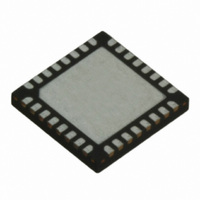
TRC105 RFM, TRC105 Datasheet - Page 59

TRC105
Manufacturer Part Number
TRC105
Description
IC TXRX 300MHZ-510MHZ 32TQFN
Manufacturer
RFM
Specifications of TRC105
Frequency
300MHz ~ 510MHz
Data Rate - Maximum
200kbps
Modulation Or Protocol
FSK, OOK
Applications
General Purpose
Power - Output
13dBm
Sensitivity
-112dBm
Voltage - Supply
2.1 V ~ 3.6 V
Current - Receiving
3mA
Current - Transmitting
30mA
Data Interface
PCB, Surface Mount
Antenna Connector
PCB, Surface Mount
Operating Temperature
-40°C ~ 85°C
Package / Case
32-TQFN
Wireless Frequency
300 MHz to 510 MHz
Output Power
13 dBm
Operating Supply Voltage
2.1 V to 3.6 V
Maximum Operating Temperature
+ 85 C
Mounting Style
SMD/SMT
Maximum Supply Current
1.7 mA
Minimum Operating Temperature
- 40 C
Modulation
FSK, OOK
Lead Free Status / RoHS Status
Lead free / RoHS Compliant
Memory Size
-
Lead Free Status / Rohs Status
Lead free / RoHS Compliant
Other names
583-1159-2
It is possible to transmit messages longer than the FIFO in Buffered data mode by monitoring the nFIFOEMPY
flag and immediately loading additional data bytes. However, messages sent by low power radios such as the
TR103 are normally 127 bytes or less to reduce the chances of corruption due to noise, fading or interference.
6.6.3 Packet Data Mode
The Packet data mode is built on top of the Buffered data mode, and adds a number of standard and optional fea-
tures:
www.RFM.com
©2009-2010 by RF Monolithics, Inc.
8. In transmit mode, IRQ0 will flag when the FIFO is empty.
9. Set IRQCFG0D bit 3 to 1. IRQ1 will flag when the last bit starts to be transmitted.
10. Load the operating frequency into register set MCFG06-MCFG08 or MCFG09-MCFG0B.
11. Select the register set to use by setting MCFG05 bit 0. A 0 value selects register set MCFG06-MCFG08
12. When ready to transmit, place the TRC105 in synthesizer mode by setting MCFG00 bits 7..5 to 010.
13. Place TRC105 in transmit mode by setting MCFG00 bits 7..5 set to 100.
14. Load the message in the FIFO through the SPI port. In Buffered data mode, the transmitted message
15. Monitor IRQ1. It sets when the when the last bit starts to be transmitted. Allow one bit period for the last
16. To prepare for receive mode, write a 1 to IRQCFG0E bit 6. This arms the start pattern detection.
17. Switch the TRC105 from standby mode to synthesizer mode by setting MCFG00 bits 7..5 set to 010.
18. Switch from synthesizer mode to receive mode by setting MCFG00 bits 7..5 to 011.
19. Following a start pattern detection, the FIFO will start filling. Note that the preamble and start pattern are
20. As each data byte is loaded into the FIFO, IRQ0 will pulse to alert the host microcontroller to retrieve
21. The host microcontroller can use a countdown on the length byte or detection of the end-of-message byte
22. As soon as all the message has been retrieved, switch the TRC105 to standby mode by setting MCFG00
23. From standby mode, enter another transmit cycle as outlined in steps 12 through 15, or enter another re-
•
•
•
•
•
and a 1 value selects register set MCFG09-MCFG0B.
Monitor the TRC105 Pin 23 to confirm PLL lock.
must include the 1-0-1-0… training preamble, the start pattern and the data. A length byte at the begin-
ning of the data or a designated end-of-message character is normally used to indicate message length.
bit to be transmitted and then switch to standby mode by setting MCFG00 bits 7..5 to 001.
Monitor the TRC105 Pin 23 to confirm PLL lock.
not loaded in the receive FIFO.
the byte.
to determine when all of the message data has been retrieved.
bits 7..5 to 001.
ceive cycle as outlined in steps 16 through 23.
Fixed or variable length packet options
Generation of preamble and start pattern (network ID) in transmit mode
DC-balancing of data by scrambling (whitening) or Manchester encoding
Generation of a 16-bit error detection CRC
Optional 1-byte node address and/or 1-byte length address
E-mail:
info@rfm.com
Technical support +1.800.704.6079
TRC105 - 11/01/10
Page 59 of 66


