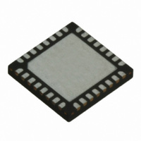
TRC105 RFM, TRC105 Datasheet - Page 25

TRC105
Manufacturer Part Number
TRC105
Description
IC TXRX 300MHZ-510MHZ 32TQFN
Manufacturer
RFM
Specifications of TRC105
Frequency
300MHz ~ 510MHz
Data Rate - Maximum
200kbps
Modulation Or Protocol
FSK, OOK
Applications
General Purpose
Power - Output
13dBm
Sensitivity
-112dBm
Voltage - Supply
2.1 V ~ 3.6 V
Current - Receiving
3mA
Current - Transmitting
30mA
Data Interface
PCB, Surface Mount
Antenna Connector
PCB, Surface Mount
Operating Temperature
-40°C ~ 85°C
Package / Case
32-TQFN
Wireless Frequency
300 MHz to 510 MHz
Output Power
13 dBm
Operating Supply Voltage
2.1 V to 3.6 V
Maximum Operating Temperature
+ 85 C
Mounting Style
SMD/SMT
Maximum Supply Current
1.7 mA
Minimum Operating Temperature
- 40 C
Modulation
FSK, OOK
Lead Free Status / RoHS Status
Lead free / RoHS Compliant
Memory Size
-
Lead Free Status / Rohs Status
Lead free / RoHS Compliant
Other names
583-1159-2
3.9.8 DC-Balanced Scrambling
A payload may contain long sequences of 1 or 0 bits. These sequences would introduce DC biases in the trans-
mitted signal, causing a non-uniform power distribution spectrum. These sequences would also degrade the per-
formance of the demodulation and data and clock recovery functions in the receiver. System performance can be
enhanced if the payload bits are randomized to reduce DC biases and increase the number of bit transitions.
As discussed above, DC-balanced data can be obtained by using Manchester encoding, which ensures that there
are no more than two consecutive 1’s or 0’s in the transmitted data. However, this reduces the effective bit-rate of
the system because it doubles the amount of data to be transmitted.
Another technique called scrambling (whitening) is widely used for randomizing data before radio transmission.
The data is scrambled using a random sequence on the transmit side and then descrambled on the receive side
using the same sequence.
The TRC105 packet handler provides a mechanism for scrambling the packet payload. A 9-bit LFSR is used to
generate a random sequence. The payload and the 16-bit CRC checksum are XOR’d with this random sequence
as shown in Figure 18. The data is descrambled on the receiver side by XORing with the same random se-
quence. The scrambling/descrambling process is enabled by setting the PKTCFG1E_Scrmb_En[4] bit to 1.
Figure 18
3.10 SPI Configuration Interface
The TRC105 contains two SPI-compatible interfaces, one to read and write the configuration registers, the other
to read and write FIFO data. Both interfaces are configured in slave mode and share the same pins: SDO (SPI
Slave Data Out), SDI (SPI Slave Data In), and SCK (Serial Clock). Two pins are provided to select the SPI con-
nection. The nSS_CONFIG pin allows access to the configuration registers and the nSS_DATA pin allows access
to the FIFO. Figure 19 shows a typical connection between a host microcontroller and the SPI interface.
www.RFM.com
E-mail:
info@rfm.com
Technical support +1.800.704.6079
Page 25 of 66
©2009-2010 by RF Monolithics, Inc.
TRC105 - 11/01/10


