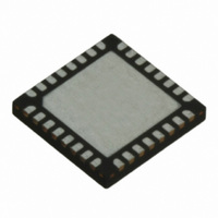
TRC105 RFM, TRC105 Datasheet - Page 19

TRC105
Manufacturer Part Number
TRC105
Description
IC TXRX 300MHZ-510MHZ 32TQFN
Manufacturer
RFM
Specifications of TRC105
Frequency
300MHz ~ 510MHz
Data Rate - Maximum
200kbps
Modulation Or Protocol
FSK, OOK
Applications
General Purpose
Power - Output
13dBm
Sensitivity
-112dBm
Voltage - Supply
2.1 V ~ 3.6 V
Current - Receiving
3mA
Current - Transmitting
30mA
Data Interface
PCB, Surface Mount
Antenna Connector
PCB, Surface Mount
Operating Temperature
-40°C ~ 85°C
Package / Case
32-TQFN
Wireless Frequency
300 MHz to 510 MHz
Output Power
13 dBm
Operating Supply Voltage
2.1 V to 3.6 V
Maximum Operating Temperature
+ 85 C
Mounting Style
SMD/SMT
Maximum Supply Current
1.7 mA
Minimum Operating Temperature
- 40 C
Modulation
FSK, OOK
Lead Free Status / RoHS Status
Lead free / RoHS Compliant
Memory Size
-
Lead Free Status / Rohs Status
Lead free / RoHS Compliant
Other names
583-1159-2
3.8 Buffered Clock Output
The buffered clock output is a signal derived from F
troller and is output on the CLKOUT pin. The OSCFG1B_Clkout_En[7] bit controls the CLKOUT pin. When this
bit is set to 1, CLKOUT is enabled, otherwise it is disabled. The output frequency of CLKOUT is defined by the
value of the OSCFG1B_Clk_freq[6..2] parameter which gives the frequency divider ratio applied to F
to Table 42 for programming details. Note: CLKOUT is disabled when the TRC105 is in sleep mode. If sleep
mode is used, the host microcontroller must have provisions to run from its own clock source.
3.9 Packet Data Mode
The TRC105 provides optional on-chip RX and TX packet handling features. These features ease the develop-
ment of packet oriented wireless communication protocols and free the MCU resources for other tasks. The op-
tions include enabling protocols based on fixed and variable packet lengths, data scrambling, CRC checksum cal-
culations and received packet filtering. All the programmable parameters of the Packet data mode are accessible
through the PKTCFG configuration registers of the device. The Packet data mode is enabled when the register bit
MCFG01_Mode[7..6 ] is set to 10 or 11.
The packet handler supports three types of packet formats: fixed length packets, variable length packets, and ex-
tended variable length packets. The PKTCFG1E_Pkt_mode[7] bit selects either the fixed or the variable length
packet formats.
3.9.1 Fixed Length Packet Mode
The fixed length packet mode is selected by setting the PKTCFG1E_Pkt_mode[7] bit to 0. In this mode the
length of the packet is set by the PKTCFG1C_Pkt_len[6..0] register up to the size of the FIFO which has been
selected.
The length stored in this register is the length of the payload which includes the message data bytes and optional
address byte. The fixed length packet format shown in Figure 13 is made up of the following fields:
www.RFM.com
©2009-2010 by RF Monolithics, Inc.
1. Preamble
2. Start pattern (network address)
3. Node address byte (optional)
4. Data bytes
5. Two-byte CRC checksum (optional)
E-mail:
info@rfm.com
IRQCFG0D_TX_IRQ1
0
1
0
1
0
1
Technical support +1.800.704.6079
Data Mode
Continuous
Continuous
Buffered
Buffered
Packet
Packet
XTAL
Table 12
Table 13
. It can be used as a reference clock for the host microcon-
Output
Output
Output
Output
Output
Output
IRQ1
IRQ0 Interrupt Source
DCLK
DCLK
FIFOFULL
TX_Stop
FIFOFULL
TX_Stop
TRC105 - 11/01/10
XTAL
Page 19 of 66
. Refer


