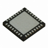
TRC105 RFM, TRC105 Datasheet - Page 22

TRC105
Manufacturer Part Number
TRC105
Description
IC TXRX 300MHZ-510MHZ 32TQFN
Manufacturer
RFM
Specifications of TRC105
Frequency
300MHz ~ 510MHz
Data Rate - Maximum
200kbps
Modulation Or Protocol
FSK, OOK
Applications
General Purpose
Power - Output
13dBm
Sensitivity
-112dBm
Voltage - Supply
2.1 V ~ 3.6 V
Current - Receiving
3mA
Current - Transmitting
30mA
Data Interface
PCB, Surface Mount
Antenna Connector
PCB, Surface Mount
Operating Temperature
-40°C ~ 85°C
Package / Case
32-TQFN
Wireless Frequency
300 MHz to 510 MHz
Output Power
13 dBm
Operating Supply Voltage
2.1 V to 3.6 V
Maximum Operating Temperature
+ 85 C
Mounting Style
SMD/SMT
Maximum Supply Current
1.7 mA
Minimum Operating Temperature
- 40 C
Modulation
FSK, OOK
Lead Free Status / RoHS Status
Lead free / RoHS Compliant
Memory Size
-
Lead Free Status / Rohs Status
Lead free / RoHS Compliant
Other names
583-1159-2
FIFO_Int_Rx when the next packet is received. Note that CRC mapping to IRQ1 is not required if the CRC state is
read from the PKTCFG1E_ CRC_stat[0] bit prior to reading the final FIFO bytes.
8. When transmitting an extended variable length packet, begin filling the FIFO until IRQ0 trips, indicating the
FIFO is half full. Add up to 32 bytes to the FIFO (64 - (MCFG05_ FIFO_thresh +1)) when IRQ0 resets. Repeat the
partial packet loading each time IRQ0 resets until all bytes to be transmitted have been clocked in. The
IRQCFG0D_TX_IRQ1[3] bit can then be set to 1, which allows the TX_STOP event to be mapped to IRQ1.
TX_STOP signals the last bit to be transmitted has been transferred the modulator. Allow one bit period for this bit
to be transmitted before switching out of transmit mode.
3.9.4 Packet Payload Processing in Transmit and Receive
The TRC105 packet handler constructs transmit packets using the payload in the FIFO. In receive, it processes
the packets and extracts the payload to the FIFO. Packet processing in transmit and receive are detailed below.
For transmit, the packet handler adds the following fields and processing to the payload in the FIFO:
The payload in the FIFO may contain one or both of the following optional fields:
If the FIFO is filled while transmit mode is enabled, and if IRQCFG0E_Start_Full[4] is set to 1, the modulator
waits until the first byte is written into the FIFO, then it starts sending the programmed preamble bytes followed by
the start pattern and the user payload. If IRQCFG0E_Start_Full[4 ] is set to 0 in the same conditions, the modu-
lator waits until the number of bytes written in the FIFO is equal to the number defined in the register MCFG05_
FIFO_thresh[5..0]. Note that the transmitter automatically sends preamble bytes in addition the number pro-
grammed while in transmit mode and waiting for the FIFO to receive the required number of bytes to start data
transmission. Data to be transmitted can also be written into the FIFO during standby mode. In this case, the data
is automatically transmitted when the transmit mode is enabled and the transmitter reaches its steady state.
If CRC is enabled, the CRC checksum is calculated over the payload bytes. This 16-bit checksum is sent after the
bytes in the FIFO. If CRC is enabled, the TX_STOP bit is set when the last CRC bit is transferred to the TX modu-
lator. If CRC is not enabled, the TX_STOP bit is set when the last bit from the FIFO is transferred to the TX modu-
lator. Note that the transmitter must remain on one bit period after the TX_STOP bit is set while the last bit is be-
ing transmitted. If the transmitter remains on following the transmission of the last bit after TX_STOP is set, the
transmitter will send preamble bytes. If Manchester encoding or scrambling is enabled, all data except the pream-
ble and start pattern is encoded or scrambled before transmission. Note that the length byte in the FIFO deter-
mines the length of the packet to be sent and the PKTCFG1C_Pkt_len[6..0] parameter is not used in transmit.
In receive, the packet handler retrieves the payload by performing the following steps:
www.RFM.com
©2009-2010 by RF Monolithics, Inc.
1. Data and clock recovery synchronization to the preamble
2. Start pattern detection
3. Optional address byte check
4. Error detection through CRC
1. One automatic preamble byte
2. One to four additional preamble bytes, programmable and usually set to 3 or 4 bytes
3. One to four start pattern bytes, programmable and usually set to at least 2 bytes
4. Optional CRC checksum calculated over the FIFO payload and appending to the end of the packet
5. Optional Manchester encoding or DC-balanced scrambling
1. A length byte if the variable packet length mode is selected
2. A node address byte
E-mail:
info@rfm.com
Technical support +1.800.704.6079
TRC105 - 11/01/10
Page 22 of 66


