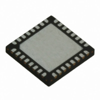
TRC105 RFM, TRC105 Datasheet - Page 57

TRC105
Manufacturer Part Number
TRC105
Description
IC TXRX 300MHZ-510MHZ 32TQFN
Manufacturer
RFM
Specifications of TRC105
Frequency
300MHz ~ 510MHz
Data Rate - Maximum
200kbps
Modulation Or Protocol
FSK, OOK
Applications
General Purpose
Power - Output
13dBm
Sensitivity
-112dBm
Voltage - Supply
2.1 V ~ 3.6 V
Current - Receiving
3mA
Current - Transmitting
30mA
Data Interface
PCB, Surface Mount
Antenna Connector
PCB, Surface Mount
Operating Temperature
-40°C ~ 85°C
Package / Case
32-TQFN
Wireless Frequency
300 MHz to 510 MHz
Output Power
13 dBm
Operating Supply Voltage
2.1 V to 3.6 V
Maximum Operating Temperature
+ 85 C
Mounting Style
SMD/SMT
Maximum Supply Current
1.7 mA
Minimum Operating Temperature
- 40 C
Modulation
FSK, OOK
Lead Free Status / RoHS Status
Lead free / RoHS Compliant
Memory Size
-
Lead Free Status / Rohs Status
Lead free / RoHS Compliant
Other names
583-1159-2
The motivation for disabling clocking when transmitting or receiving OOK is that non-standard bit rates can be
used. However, the host microcontroller must handle the data and clock recovery functions. When using continu-
ous mode with or without clocking enabled, data should be encoded to provide DC-balance (same number of 1
and 0 bits) and limited run lengths of the same bit value. Manchester encoding, 8-to-12 bit symbolizing or scram-
bling must be applied to the data before transmitting and removed after receiving to achieve good RF transmis-
sion performance. The preamble, start pattern and error checking bits must also be generated by the host micro-
controller to establish robust data communications.
6.6.2 Buffered Data Mode
In Buffered data mode operation, the transmitted and received data bits pass through the SPI port in groups of
8 bits to the internal TRC105 FIFO. Bits flow from the FIFO to the modulator for transmission and are loaded into
the FIFO as data is received. As discussed in Sections 3.10 and 3.11, the SPI port can address the data FIFO or
the configuration registers. Asserting a logic low on the nSS_DATA input addresses the FIFO, and asserting a
logic low on the nSS_CONFIG addresses the configuration registers. If both of these inputs are asserted,
nSS_CONFIG will override nSS_DATA. The TRC105 acts as an SPI slave and receives clocking from its host
microcontroller. SPI read/write details are provided in Sections 3.10 and 3.11. As shown in Figure 19, two inter-
rupt (control) outputs, IRQ0 and IRQ1, are provided by the TRC105 to coordinate SPI data flow to and from the
host microcontroller. One to four signals can selected or mapped to each interrupt output. This mapping is config-
ured in register IRQCFG0D. Bits 7..6 select the signal for IRQ0 in the receive mode, and Bit 3 selects the IRQ0
signal in transmit mode. Bits 5..4 select the signal for IRQ1 in the receive mode, and Bit 2 selects the IRQ1 signal
in transmit mode. The mapping options for Buffered data mode are summarized in Table 78:
www.RFM.com
©2009-2010 by RF Monolithics, Inc.
E-mail:
IRQCFG0D bits
7..6
7..6
7..6
7..6
5..4
5..4
5..4
5..4
3
3
2
2
info@rfm.com
IRQCFG0D bits
Cfg
00
01
10
11
00
01
10
11
1
0
0
1
7..6
7..6
5..4
3
2
State
RX
RX
RX
RX
RX
RX
RX
RX
TX
TX
TX
TX
00, 1X
Technical support +1.800.704.6079
Cfg
XX
01
X
X
IRQ
0
0
0
0
0
1
1
1
1
0
1
1
State
RX
RX
RX
TX
TX
Write_byte (high pulse when received byte written to FIFO)
Table 77
Table 78
IRQ
0
0
0
1
1
Start Pattern Detect
Start Pattern Detect
nFIFOEMPTY
nFIFOEMPTY
FIFO_Int_Rx
FIFO_Int_Tx
no signal (0)
no signal (0)
FIFOFULL
FIFOFULL
RSSI_IRQ
no signal (0)
TX_Stop
Source
Source
DCLK
DCLK
RSSI
TRC105 - 11/01/10
Page 57 of 66


