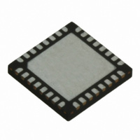
TRC105 RFM, TRC105 Datasheet - Page 10

TRC105
Manufacturer Part Number
TRC105
Description
IC TXRX 300MHZ-510MHZ 32TQFN
Manufacturer
RFM
Specifications of TRC105
Frequency
300MHz ~ 510MHz
Data Rate - Maximum
200kbps
Modulation Or Protocol
FSK, OOK
Applications
General Purpose
Power - Output
13dBm
Sensitivity
-112dBm
Voltage - Supply
2.1 V ~ 3.6 V
Current - Receiving
3mA
Current - Transmitting
30mA
Data Interface
PCB, Surface Mount
Antenna Connector
PCB, Surface Mount
Operating Temperature
-40°C ~ 85°C
Package / Case
32-TQFN
Wireless Frequency
300 MHz to 510 MHz
Output Power
13 dBm
Operating Supply Voltage
2.1 V to 3.6 V
Maximum Operating Temperature
+ 85 C
Mounting Style
SMD/SMT
Maximum Supply Current
1.7 mA
Minimum Operating Temperature
- 40 C
Modulation
FSK, OOK
Lead Free Status / RoHS Status
Lead free / RoHS Compliant
Memory Size
-
Lead Free Status / Rohs Status
Lead free / RoHS Compliant
Other names
583-1159-2
2.5 Frequency Synthesizer
The TRC105 VCO operating frequency range is covered in six bands. Operation in each band requires a specific
VCO inductor value and configuration parameter setting, as shown in Table 4 below:
Each of these bands is divided into four subbands to provide a low phase noise VCO frequency trimming mecha-
nism. Subbands are selected as shown in Table 5 below:
Using the VCO as discussed above, the frequency synthesizer generates the local oscillator (LO) signal for the
receiver and transmitter sections. The core of the synthesizer is implemented with an integer-N PLL architecture.
The frequency is set by three divider parameters R, P and S. R is the frequency divider ratio in the reference fre-
quency path. P and S set the frequency divider ratio in the feedback loop of the PLL. The frequency synthesizer
includes a crystal oscillator which provides the frequency reference for the PLL. The equations giving the relation-
ships between the reference crystal frequency, the local oscillator frequency and RF carrier frequency are given
below:
F
frequency. F
the transmitter. The intermediate frequency used for the second down-conversion of the receiver and the first up-
conversion of the transmitter is equal to 1/8 of F
RF frequency of 434 MHz, F
There are two sets of divider ratio registers: SynthR1[7..0], SynthP1[7..0], SynthS1[7..0], and SynthR2[7..0],
SynthP2[7..0], SynthS2[7..0]. The MCFG05_RF_Freq[0] bit is used to select which set of registers to use as the
current frequency setting. For frequency hopping applications, this reduces the programming and synthesizer set-
tling time when changing frequencies. While the data is being transmitted, the next frequency is programmed and
ready. When the current transaction is complete, the MCFG05_RF_Freq[0] bit is complemented and the fre-
quency shifts to the next freq according to the contents of the divider ratio registers. This process is repeated for
each frequency hop.
www.RFM.com
©2009-2010 by RF Monolithics, Inc.
LO
is the first local oscillator (VCO) frequency, F
F
range 64 to 169, and F
F
LO
RF
= F
= 1.125*F
LO
E-mail:
is the frequency used for the first down-conversion of the receiver and the second up-conversion of
XTAL
*(75*(P + 1) + S)/(R + 1), with P and S in the range 0 to 255, S less than (P + 1), R in the
info@rfm.com
LO
, where F
LO
MCFG00_Subband[1..0]
is 385.8 MHz and the first IF of the receiver is 48.2 MHz.
LO
RF
and F
and F
MCFG00_Band[4..2]
00
01
10
11
XTAL
LO
110 to 111
in MHz.
Technical support +1.800.704.6079
are in MHz
000
001
010
011
100
101
LO
XTAL
. As an example, with a crystal frequency of 12.8 MHz and an
is the reference crystal frequency and F
Table 4
2
Table 5
1
3
4
Subband
nd
st
rd
th
quarter
quarter
quarter
quarter
Frequency Band MHz
not used
300-330
330-365
365-400
400-440
440-470
470-510
400-440 MHz example
400-410
410-420
420-430
430-440
RF
is the RF channel
TRC105 - 11/01/10
Page 10 of 66


