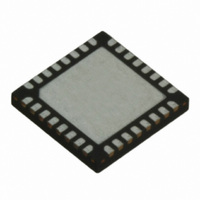
TRC105 RFM, TRC105 Datasheet - Page 52

TRC105
Manufacturer Part Number
TRC105
Description
IC TXRX 300MHZ-510MHZ 32TQFN
Manufacturer
RFM
Specifications of TRC105
Frequency
300MHz ~ 510MHz
Data Rate - Maximum
200kbps
Modulation Or Protocol
FSK, OOK
Applications
General Purpose
Power - Output
13dBm
Sensitivity
-112dBm
Voltage - Supply
2.1 V ~ 3.6 V
Current - Receiving
3mA
Current - Transmitting
30mA
Data Interface
PCB, Surface Mount
Antenna Connector
PCB, Surface Mount
Operating Temperature
-40°C ~ 85°C
Package / Case
32-TQFN
Wireless Frequency
300 MHz to 510 MHz
Output Power
13 dBm
Operating Supply Voltage
2.1 V to 3.6 V
Maximum Operating Temperature
+ 85 C
Mounting Style
SMD/SMT
Maximum Supply Current
1.7 mA
Minimum Operating Temperature
- 40 C
Modulation
FSK, OOK
Lead Free Status / RoHS Status
Lead free / RoHS Compliant
Memory Size
-
Lead Free Status / Rohs Status
Lead free / RoHS Compliant
Other names
583-1159-2
such as the TRC105’s data scrambling or Manchester encoding options. The average-referenced threshold run-
ning with a chip rate/2*π cutoff frequency is a good choice for the majority of OOK applications.
The peak-referenced threshold is generated from the RSSI signal using a fast attack, slow decay peak detector
emulation. The slicer threshold is immediately set to 6 dB below the peak value of the RSSI signal anytime the
RSSI value exceeds the threshold by 6 dB. The threshold then decays by a configurable dB step when a config-
urable interval passes without the RSSI signal peaking 6 dB above the threshold. The decay step is configured
with RXCFG15 bits 7..5 as shown in Table 65:
The decay interval is configured with RXCFG15 bits 4..2 as shown in Table 66:
The chip period t
ing, the chip period is equal to ½ the bit period:
Where t
provide a good starting point for most applications. For application environments that contain pulse noise, such as
operation in a band where other FHSS systems are operating, using Manchester encoding and decreasing the
decay interval to twice or four times per chip and/or increasing the decay step to 1 dB will reduce the “blinding”
effect of pulse noise. Multipath flutter tolerance is also improved by using Manchester encoding and decreasing
the decay interval and/or increasing the decay step size.
6.3.3 OOK Transmitter Related Configuration Values
MCFG05 bits 7..6 allow the rise and fall time of the power amplifier regulator to be adjusted. Using the default
component values for R6 and C5 as shown in Figure 2, the rise and fall times for the power amplifier regulator
and the OOK modulation are given in Table 67:
www.RFM.com
©2009-2010 by RF Monolithics, Inc.
CP
t
CP
is in ms and BR is in kb/s. The default values of 0.5 dB per decay step and 1 decay interval per chip
= 1/BR without Manchester encoding, t
E-mail:
CP
is equal to the bit period except when Manchester encoding is used. For Manchester encod-
info@rfm.com
Pattern of Bits 7..5
Pattern of Bits 4..2
Technical support +1.800.704.6079
000
001
010
011
100
101
110
111
000
001
010
011
100
101
110
111
CP
Table 65
Table 66
= 1/(2*BR) with Manchester encoding
four times per chip
16 times per chip
once per 2 chips
once per 4 chips
once per 8 chips
8 times per chip
Decay Interval
twice per chip
once per chip
Decay Step
0.5 dB
1.0 dB
1.5 dB
2.0 dB
3.0 dB
4.0 dB
5.0 dB
6.0 dB
TRC105 - 11/01/10
Page 52 of 66


