R5F21324ANSP#U1 Renesas Electronics America, R5F21324ANSP#U1 Datasheet - Page 548
R5F21324ANSP#U1
Manufacturer Part Number
R5F21324ANSP#U1
Description
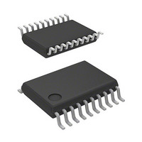
MCU 1KB FLASH 16K ROM 20-LSSOP
Manufacturer
Renesas Electronics America
Series
R8C/3x/32Ar
Datasheet
1.R5F21322ANSPU1.pdf
(629 pages)
Specifications of R5F21324ANSP#U1
Core Processor
R8C
Core Size
16/32-Bit
Speed
20MHz
Connectivity
I²C, LIN, SIO, SSU, UART/USART
Peripherals
POR, PWM, Voltage Detect, WDT
Number Of I /o
15
Program Memory Size
16KB (16K x 8)
Program Memory Type
FLASH
Ram Size
1.5K x 8
Voltage - Supply (vcc/vdd)
1.8 V ~ 5.5 V
Data Converters
A/D 4x10b
Oscillator Type
Internal
Operating Temperature
-20°C ~ 85°C
Package / Case
20-LSSOP
Lead Free Status / RoHS Status
Lead free / RoHS Compliant
Eeprom Size
-
Available stocks
Company
Part Number
Manufacturer
Quantity
Price


Under development
R8C/32A Group
REJ09B0458-0020 Rev.0.20
Page 518 of 583
Figure 30.17
Table 30.8
VCC, VSS
RESET
P4_6/XIN/(XCIN)
P4_7/XOUT/(XCOUT) P4_7 input/clock output I/O
P1_0 to P1_7
P3_3 to P3_5, P3_7
P4_2/VREF, P4_5
MODE
Pin
Pin Handling in Standard Serial I/O Mode 3
Preliminary specification
Specifications in this manual are tentative and subject to change.
Pin Functions (Flash Memory Standard Serial I/O Mode 3)
Notes:
Reset input
MODE I/O
1. Controlled pins and external circuits vary depending on the programmer.
2. In this example, modes are switched between single-chip mode and
3. When operating with the on-chip oscillator clock, it is not necessary to
Refer to the programmer manual for details.
Power supply input
Reset input
P4_6 input/clock input
Input port P1
Input port P3
Input port P4
MODE
standard serial I/O mode by connecting a programmer.
connect an oscillation circuit.
Nov 05, 2008
Name
User reset signal
I/O
I/O Serial data I/O pin. Connect the pin to a
I
I
I
I
I
Apply the guaranteed programming and erasure
voltage to the VCC pin and 0 V to the VSS pin.
Reset input pin
If an external oscillator is connected, connect a
ceramic resonator or crystal oscillator between pins
XIN(XCIN) and XOUT(XCOUT).
To use as an input port, input a “H” or “L” level
signal or leave the pin open.
Input a “H” or “L” level signal or leave open.
Input a “H” or “L” level signal or leave open.
Input a “H” or “L” level signal or leave open.
programmer.
MODE
RESET
MCU
AVCC
AVSS
VCC
VSS
Description
30. Flash Memory
Related parts for R5F21324ANSP#U1
Image
Part Number
Description
Manufacturer
Datasheet
Request
R

Part Number:
Description:
KIT STARTER FOR M16C/29
Manufacturer:
Renesas Electronics America
Datasheet:

Part Number:
Description:
KIT STARTER FOR R8C/2D
Manufacturer:
Renesas Electronics America
Datasheet:

Part Number:
Description:
R0K33062P STARTER KIT
Manufacturer:
Renesas Electronics America
Datasheet:

Part Number:
Description:
KIT STARTER FOR R8C/23 E8A
Manufacturer:
Renesas Electronics America
Datasheet:

Part Number:
Description:
KIT STARTER FOR R8C/25
Manufacturer:
Renesas Electronics America
Datasheet:

Part Number:
Description:
KIT STARTER H8S2456 SHARPE DSPLY
Manufacturer:
Renesas Electronics America
Datasheet:

Part Number:
Description:
KIT STARTER FOR R8C38C
Manufacturer:
Renesas Electronics America
Datasheet:

Part Number:
Description:
KIT STARTER FOR R8C35C
Manufacturer:
Renesas Electronics America
Datasheet:

Part Number:
Description:
KIT STARTER FOR R8CL3AC+LCD APPS
Manufacturer:
Renesas Electronics America
Datasheet:
Part Number:
Description:
KIT STARTER FOR RX610
Manufacturer:
Renesas Electronics America
Datasheet:

Part Number:
Description:
KIT STARTER FOR R32C/118
Manufacturer:
Renesas Electronics America
Datasheet:

Part Number:
Description:
KIT DEV RSK-R8C/26-29
Manufacturer:
Renesas Electronics America
Datasheet:

Part Number:
Description:
KIT STARTER FOR SH7124
Manufacturer:
Renesas Electronics America
Datasheet:

Part Number:
Description:
KIT STARTER FOR H8SX/1622
Manufacturer:
Renesas Electronics America
Datasheet:

Part Number:
Description:
KIT DEV FOR SH7203
Manufacturer:
Renesas Electronics America
Datasheet: