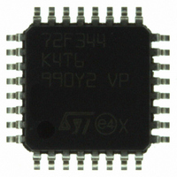
ST72F344K4T6 STMicroelectronics, ST72F344K4T6 Datasheet - Page 29

ST72F344K4T6
Manufacturer Part Number
ST72F344K4T6
Description
MCU 8BIT 16KB FLASH MEM 32-LQFP
Manufacturer
STMicroelectronics
Series
ST7r
Datasheet
1.ST72F344K2T6.pdf
(247 pages)
Specifications of ST72F344K4T6
Core Processor
ST7
Core Size
8-Bit
Speed
8MHz
Connectivity
I²C, LIN, SCI, SPI
Peripherals
LVD, POR, PWM, WDT
Number Of I /o
24
Program Memory Size
16KB (16K x 8)
Program Memory Type
FLASH
Eeprom Size
256 x 8
Ram Size
1K x 8
Voltage - Supply (vcc/vdd)
2.7 V ~ 5.5 V
Data Converters
A/D 12x10b
Oscillator Type
Internal
Operating Temperature
-40°C ~ 85°C
Package / Case
32-LQFP
Processor Series
ST72F3x
Core
ST7
Data Bus Width
8 bit
Data Ram Size
1 KB
Interface Type
I2C, SCI, SPI
Maximum Clock Frequency
8 MHz
Number Of Programmable I/os
34
Number Of Timers
2
Maximum Operating Temperature
+ 85 C
Mounting Style
SMD/SMT
Development Tools By Supplier
ST72F34X-SK/RAIS, ST7MDT40-EMU3, STX-RLINK
Minimum Operating Temperature
- 40 C
On-chip Adc
10 bit, 8 Channel
For Use With
497-5046 - KIT TOOL FOR ST7/UPSD/STR7 MCU
Lead Free Status / RoHS Status
Lead free / RoHS Compliant
Other names
497-5611
Available stocks
Company
Part Number
Manufacturer
Quantity
Price
Company:
Part Number:
ST72F344K4T6
Manufacturer:
STMicroelectronics
Quantity:
10 000
Company:
Part Number:
ST72F344K4T6TR
Manufacturer:
STMicroelectronics
Quantity:
10 000
- Current page: 29 of 247
- Download datasheet (3Mb)
ST72344xx ST72345xx
Caution:
4.5
4.5.1
3
4
5
isolate the application reset circuit in this case. When using a classical RC network with
R>1K or a reset management IC with open drain output and pull-up resistor>1K, no
additional components are needed. In all cases the user must ensure that no external reset
is generated by the application during the ICC session.
The use of Pin 7 of the ICC connector depends on the Programming Tool architecture. This
pin must be connected when using most ST Programming Tools (it is used to monitor the
application power supply). Please refer to the Programming Tool manual.
Pin 9 has to be connected to the OSC1 pin of the ST7 when the clock is not available in the
application or if the selected clock option is not programmed in the option byte. ST7 devices
with multi-oscillator capability need to have OSC2 grounded in this case.
In “enabled option byte” mode (38-pulse ICC mode), the internal RC oscillator is forced as a
clock source, regardless of the selection in the option byte.
During normal operation the ICCCLK pin must be internally or externally pulled- up (external
pull-up of 10 kΩ mandatory in noisy environment) to avoid entering ICC mode unexpectedly
during a reset. In the application, even if the pin is configured as output, any reset will put it
back in input pull-up.
Figure 6.
Memory protection
There are two different types of memory protection: Read Out Protection and Write/Erase
Protection which can be applied individually.
Readout protection
Readout protection, when selected provides a protection against program memory content
extraction and against write access to Flash memory. Even if no protection can be
considered as totally unbreakable, the feature provides a very high level of protection for a
general purpose microcontroller. Both program and data E
POWER SUPPLY
APPLICATION
Typical ICC interface
(See Note 3)
C
L2
Doc ID 12321 Rev 5
OPTIONAL
(See Note 4)
C
ST7
L1
HE10 CONNECTOR TYPE
10kΩ
ICC CONNECTOR
10
9
PROGRAMMING TOOL
ICC CONNECTOR
7
8
5
6
4
3
ICC Cable
1
2
2
memory are protected.
See Note 1
APPLICATION BOARD
Flash program memory
APPLICATION
RESET SOURCE
See Note 2
APPLICATION
I/O
29/247
Related parts for ST72F344K4T6
Image
Part Number
Description
Manufacturer
Datasheet
Request
R

Part Number:
Description:
STMicroelectronics [RIPPLE-CARRY BINARY COUNTER/DIVIDERS]
Manufacturer:
STMicroelectronics
Datasheet:

Part Number:
Description:
STMicroelectronics [LIQUID-CRYSTAL DISPLAY DRIVERS]
Manufacturer:
STMicroelectronics
Datasheet:

Part Number:
Description:
BOARD EVAL FOR MEMS SENSORS
Manufacturer:
STMicroelectronics
Datasheet:

Part Number:
Description:
NPN TRANSISTOR POWER MODULE
Manufacturer:
STMicroelectronics
Datasheet:

Part Number:
Description:
TURBOSWITCH ULTRA-FAST HIGH VOLTAGE DIODE
Manufacturer:
STMicroelectronics
Datasheet:

Part Number:
Description:
Manufacturer:
STMicroelectronics
Datasheet:

Part Number:
Description:
DIODE / SCR MODULE
Manufacturer:
STMicroelectronics
Datasheet:

Part Number:
Description:
DIODE / SCR MODULE
Manufacturer:
STMicroelectronics
Datasheet:

Part Number:
Description:
Search -----> STE16N100
Manufacturer:
STMicroelectronics
Datasheet:

Part Number:
Description:
Search ---> STE53NA50
Manufacturer:
STMicroelectronics
Datasheet:

Part Number:
Description:
NPN Transistor Power Module
Manufacturer:
STMicroelectronics
Datasheet:

Part Number:
Description:
DIODE / SCR MODULE
Manufacturer:
STMicroelectronics
Datasheet:


