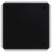
MCF5407AI220 Freescale Semiconductor, MCF5407AI220 Datasheet - Page 510

MCF5407AI220
Manufacturer Part Number
MCF5407AI220
Description
IC MPU 32B 220MHZ COLDF 208-FQFP
Manufacturer
Freescale Semiconductor
Series
MCF540xr
Specifications of MCF5407AI220
Core Processor
Coldfire V4
Core Size
32-Bit
Speed
220MHz
Connectivity
EBI/EMI, I²C, UART/USART
Peripherals
DMA, WDT
Number Of I /o
16
Program Memory Type
ROMless
Ram Size
4K x 8
Voltage - Supply (vcc/vdd)
1.65 V ~ 3.6 V
Oscillator Type
External
Operating Temperature
0°C ~ 70°C
Package / Case
208-FQFP
Maximum Clock Frequency
220 MHz
Operating Supply Voltage
1.8 V, 3.3 V
Maximum Operating Temperature
+ 105 C
Mounting Style
SMD/SMT
Minimum Operating Temperature
0 C
Program Memory Size
24KB
Cpu Speed
220MHz
Embedded Interface Type
I2C, UART
Digital Ic Case Style
FQFP
No. Of Pins
208
Supply Voltage Range
3.3V
Rohs Compliant
Yes
For Use With
M5407C3 - KIT EVAL FOR MCF5407 W/ETHERNET
Lead Free Status / RoHS Status
Lead free / RoHS Compliant
Eeprom Size
-
Program Memory Size
-
Data Converters
-
Lead Free Status / Rohs Status
Lead free / RoHS Compliant
Available stocks
Company
Part Number
Manufacturer
Quantity
Price
Company:
Part Number:
MCF5407AI220
Manufacturer:
freescaie
Quantity:
6
Company:
Part Number:
MCF5407AI220
Manufacturer:
Freescale Semiconductor
Quantity:
135
Company:
Part Number:
MCF5407AI220
Manufacturer:
FREESCALE
Quantity:
1 831
Company:
Part Number:
MCF5407AI220
Manufacturer:
Freescale Semiconductor
Quantity:
10 000
- Current page: 510 of 546
- Download datasheet (7Mb)
Reset Initialization Modifications
BCLKO runs at the same frequency as CLKIN and is offered as an optional timing
reference for backwards compatibility for lower-speed MCF5307 designs.
Regardless of the CLKIN frequency driven at power-up, CLKIN and BCLKO have the
same ratio value to PCLK. Although designers can use either BCLKO or CLKIN as a clock
reference, Motorola recommends using CLKIN because it leaves more room to meet bus
specifications than BCLKO, which is generated as a phase-aligned signal to CLKIN. An
MCF5307 user should consider switching to a CLKIN reference clock when upgrading to
the MCF5407 if board frequencies exceed 50 MHz.
Although the CLKIN duty cycle remains the same for the MCF5307 and MCF5407, use
caution when interfacing signals on the falling edge of CLKIN with only a 4-nS window at
high frequencies. Also, note that the MCF5407 input rise time is reduced to 2 nS (5 nS in
the MCF5307). For designers who choose to reference signals from CLKIN only, BCLKO
can be disabled to save power. For details see Section 7.2.3, “Reduced-Power Mode”.
A.7 Reset Initialization Modifications
Like the MCF5307, the MCF5407 samples a group of eight input signals, D[7:0], on the
rising edge of CLKIN before the rising edge of RSTI to determine the reset configuration
of the global chip select, the address bus, and PLL. However, unlike the MCF5307, the
frequency range encodings are not sampled on D[3:2], which are replaced by two other
reset configuration inputs. First, the CLKIN-to-PCLK ratio allows more combinations.
This extra bit is now sampled on D2 so that the clock ratio programming bits encompass
D[2:0]/DIVIDE[2:0].
Second, a new reset configuration bit, BE_CONFIG, is now multiplexed with D3 in the
MCF5407. This bit enables the four byte enables for the global chip select, CS0, for reads
and writes or writes only, depending on the bit value sampled at reset, as shown in
Table A-10.
Table A-6 shows the multiplexing of D[7:0] for the MCF5307 and the MCF5407.
Table A-7 through Table A-10 list the various reset encodings for the configuration signals
A-8
Data Pins
D[6:5]
D7
D4
D3
D2
D1
D0
Table A-6. D[7:0] Multiplexing
MCF5407 User’s Manual
MCF5307
FREQ1
FREQ0
ADDR_CONFIG
DIVIDE1
DIVIDE0
PS[1:0]
AA
BE_CONFIG, BE[3:0]
MCF5407
DIVIDE2
Related parts for MCF5407AI220
Image
Part Number
Description
Manufacturer
Datasheet
Request
R
Part Number:
Description:
Mcf5407 Coldfire Integrated Microprocessor User
Manufacturer:
Freescale Semiconductor, Inc
Datasheet:
Part Number:
Description:
Manufacturer:
Freescale Semiconductor, Inc
Datasheet:
Part Number:
Description:
Manufacturer:
Freescale Semiconductor, Inc
Datasheet:
Part Number:
Description:
Manufacturer:
Freescale Semiconductor, Inc
Datasheet:
Part Number:
Description:
Manufacturer:
Freescale Semiconductor, Inc
Datasheet:
Part Number:
Description:
Manufacturer:
Freescale Semiconductor, Inc
Datasheet:
Part Number:
Description:
Manufacturer:
Freescale Semiconductor, Inc
Datasheet:
Part Number:
Description:
Manufacturer:
Freescale Semiconductor, Inc
Datasheet:
Part Number:
Description:
Manufacturer:
Freescale Semiconductor, Inc
Datasheet:
Part Number:
Description:
Manufacturer:
Freescale Semiconductor, Inc
Datasheet:
Part Number:
Description:
Manufacturer:
Freescale Semiconductor, Inc
Datasheet:
Part Number:
Description:
Manufacturer:
Freescale Semiconductor, Inc
Datasheet:
Part Number:
Description:
Manufacturer:
Freescale Semiconductor, Inc
Datasheet:
Part Number:
Description:
Manufacturer:
Freescale Semiconductor, Inc
Datasheet:
Part Number:
Description:
Manufacturer:
Freescale Semiconductor, Inc
Datasheet:


