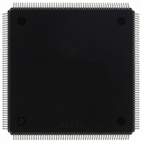
MCF5407AI220 Freescale Semiconductor, MCF5407AI220 Datasheet - Page 349

MCF5407AI220
Manufacturer Part Number
MCF5407AI220
Description
IC MPU 32B 220MHZ COLDF 208-FQFP
Manufacturer
Freescale Semiconductor
Series
MCF540xr
Specifications of MCF5407AI220
Core Processor
Coldfire V4
Core Size
32-Bit
Speed
220MHz
Connectivity
EBI/EMI, I²C, UART/USART
Peripherals
DMA, WDT
Number Of I /o
16
Program Memory Type
ROMless
Ram Size
4K x 8
Voltage - Supply (vcc/vdd)
1.65 V ~ 3.6 V
Oscillator Type
External
Operating Temperature
0°C ~ 70°C
Package / Case
208-FQFP
Maximum Clock Frequency
220 MHz
Operating Supply Voltage
1.8 V, 3.3 V
Maximum Operating Temperature
+ 105 C
Mounting Style
SMD/SMT
Minimum Operating Temperature
0 C
Program Memory Size
24KB
Cpu Speed
220MHz
Embedded Interface Type
I2C, UART
Digital Ic Case Style
FQFP
No. Of Pins
208
Supply Voltage Range
3.3V
Rohs Compliant
Yes
For Use With
M5407C3 - KIT EVAL FOR MCF5407 W/ETHERNET
Lead Free Status / RoHS Status
Lead free / RoHS Compliant
Eeprom Size
-
Program Memory Size
-
Data Converters
-
Lead Free Status / Rohs Status
Lead free / RoHS Compliant
Available stocks
Company
Part Number
Manufacturer
Quantity
Price
Company:
Part Number:
MCF5407AI220
Manufacturer:
freescaie
Quantity:
6
Company:
Part Number:
MCF5407AI220
Manufacturer:
Freescale Semiconductor
Quantity:
135
Company:
Part Number:
MCF5407AI220
Manufacturer:
FREESCALE
Quantity:
1 831
Company:
Part Number:
MCF5407AI220
Manufacturer:
Freescale Semiconductor
Quantity:
10 000
- Current page: 349 of 546
- Download datasheet (7Mb)
14.3.2 UART Mode Register 2 (UMR2n)
UART mode registers 2 (UMR2n) control UART module configuration. UMR2n can be
read or written when the mode register pointer points to it, which occurs after any access to
UMR1n. UMR2n accesses do not update the pointer.
Table 14-3 describes UMR2n fields.
Bits
7–6
Address
5
4
Reset
Field
R/W
TxRTS Transmitter ready-to-send. Controls negation of RTS to automatically terminate a message
TxCTS Transmitter clear-to-send. If both TxCTS and TxRTS are enabled, TxCTS controls the operation of the
Name
CM
Channel mode. Selects a channel mode. Section 14.5.3, “Looping Modes,” describes individual
modes. CM is used in both UART and modem modes.
00 Normal
01 Automatic echo
10 Local loop-back
11 Remote loop-back
transmission. Attempting to program a receiver and transmitter in the same channel for RTS control is
not permitted and disables RTS control for both. TxRTS is not used in modem mode.
0 The transmitter has no effect on RTS.
1 In applications where the transmitter is disabled after transmission completes, setting this bit
transmitter. TxCTS is not used in modem mode.
0 CTS has no effect on the transmitter.
1 Enables clear-to-send operation. The transmitter checks the state of CTS each time it is ready to
7
automatically clears UOP[RTS] one bit time after any characters in the channel transmitter shift and
holding registers are completely sent, including the programmed number of stop bits.
send a character. If CTS is asserted, the character is sent; if it is negated, the channel TxD remains
in the high state and transmission is delayed until CTS is asserted. Changes in CTS as a character is
being sent do not affect its transmission.
MBAR + 0x1C0, 0x200. After UMR1n is read or written, the pointer points to UMR2n.
CM
Figure 14-3. UART Mode Register 2 (UMR2n)
6
Table 14-3. UMR2n Field Descriptions
TxRTS
Chapter 14. UART Modules
5
TxCTS
4
0000_0000
Description
R/W
3
SB
Register Descriptions
0
14-7
Related parts for MCF5407AI220
Image
Part Number
Description
Manufacturer
Datasheet
Request
R
Part Number:
Description:
Mcf5407 Coldfire Integrated Microprocessor User
Manufacturer:
Freescale Semiconductor, Inc
Datasheet:
Part Number:
Description:
Manufacturer:
Freescale Semiconductor, Inc
Datasheet:
Part Number:
Description:
Manufacturer:
Freescale Semiconductor, Inc
Datasheet:
Part Number:
Description:
Manufacturer:
Freescale Semiconductor, Inc
Datasheet:
Part Number:
Description:
Manufacturer:
Freescale Semiconductor, Inc
Datasheet:
Part Number:
Description:
Manufacturer:
Freescale Semiconductor, Inc
Datasheet:
Part Number:
Description:
Manufacturer:
Freescale Semiconductor, Inc
Datasheet:
Part Number:
Description:
Manufacturer:
Freescale Semiconductor, Inc
Datasheet:
Part Number:
Description:
Manufacturer:
Freescale Semiconductor, Inc
Datasheet:
Part Number:
Description:
Manufacturer:
Freescale Semiconductor, Inc
Datasheet:
Part Number:
Description:
Manufacturer:
Freescale Semiconductor, Inc
Datasheet:
Part Number:
Description:
Manufacturer:
Freescale Semiconductor, Inc
Datasheet:
Part Number:
Description:
Manufacturer:
Freescale Semiconductor, Inc
Datasheet:
Part Number:
Description:
Manufacturer:
Freescale Semiconductor, Inc
Datasheet:
Part Number:
Description:
Manufacturer:
Freescale Semiconductor, Inc
Datasheet:


