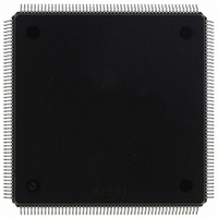
MCF5407AI220 Freescale Semiconductor, MCF5407AI220 Datasheet - Page 329

MCF5407AI220
Manufacturer Part Number
MCF5407AI220
Description
IC MPU 32B 220MHZ COLDF 208-FQFP
Manufacturer
Freescale Semiconductor
Series
MCF540xr
Specifications of MCF5407AI220
Core Processor
Coldfire V4
Core Size
32-Bit
Speed
220MHz
Connectivity
EBI/EMI, I²C, UART/USART
Peripherals
DMA, WDT
Number Of I /o
16
Program Memory Type
ROMless
Ram Size
4K x 8
Voltage - Supply (vcc/vdd)
1.65 V ~ 3.6 V
Oscillator Type
External
Operating Temperature
0°C ~ 70°C
Package / Case
208-FQFP
Maximum Clock Frequency
220 MHz
Operating Supply Voltage
1.8 V, 3.3 V
Maximum Operating Temperature
+ 105 C
Mounting Style
SMD/SMT
Minimum Operating Temperature
0 C
Program Memory Size
24KB
Cpu Speed
220MHz
Embedded Interface Type
I2C, UART
Digital Ic Case Style
FQFP
No. Of Pins
208
Supply Voltage Range
3.3V
Rohs Compliant
Yes
For Use With
M5407C3 - KIT EVAL FOR MCF5407 W/ETHERNET
Lead Free Status / RoHS Status
Lead free / RoHS Compliant
Eeprom Size
-
Program Memory Size
-
Data Converters
-
Lead Free Status / Rohs Status
Lead free / RoHS Compliant
Available stocks
Company
Part Number
Manufacturer
Quantity
Price
Company:
Part Number:
MCF5407AI220
Manufacturer:
freescaie
Quantity:
6
Company:
Part Number:
MCF5407AI220
Manufacturer:
Freescale Semiconductor
Quantity:
135
Company:
Part Number:
MCF5407AI220
Manufacturer:
FREESCALE
Quantity:
1 831
Company:
Part Number:
MCF5407AI220
Manufacturer:
Freescale Semiconductor
Quantity:
10 000
- Current page: 329 of 546
- Download datasheet (7Mb)
12.5.4.2 Auto-Alignment
Auto-alignment allows block transfers to occur at the optimal size based on the address,
byte count, and programmed size. To use this feature, DCR[AA] must be set. The source is
auto-aligned if SSIZE indicates a transfer size larger than DSIZE. Source alignment takes
precedence over the destination when the source and destination sizes are equal. Otherwise,
the destination is auto-aligned. The address register chosen for alignment increments
regardless of the increment value. Configuration error checking is performed on registers
not chosen for alignment.
If BCR is greater than 16, the address determines transfer size. Bytes, words, or longwords
are transferred until the address is aligned to the programmed size boundary, at which time
accesses begin using the programmed size.
If BCR is less than 16 at the start of a transfer, the number of bytes remaining dictates
transfer size. For example, AA = 1, SAR = 0x0001, BCR = 0x00F0, SSIZE = 00
(longword), and DSIZE = 01 (byte). Because SSIZE > DSIZE, the source is auto-aligned.
Error checking is performed on destination registers. The access sequence is as follows:
A[31:0], SIZ[1:0]
1. Read byte from 0x0001—write 1 byte, increment SAR.
2. Read word from 0x0002—write 2 bytes, increment SAR.
3. Read longword from 0x0004—write 4 bytes, increment SAR.
4. Repeat longwords until SAR = 0x00F0.
OE, BE/BWE
TM0/DACK0
CSx, AS
DREQ0
D[31:0]
CLKIN
TM2
R/W
TT0
TT1
TIP
TS
TA
0
Figure 12-13. Single-Address DMA Transfer
1
Chapter 12. DMA Controller Module
2
3
4
5
DMA Controller Module Functional Description
6
7
8
9
10
11
12-17
Related parts for MCF5407AI220
Image
Part Number
Description
Manufacturer
Datasheet
Request
R
Part Number:
Description:
Mcf5407 Coldfire Integrated Microprocessor User
Manufacturer:
Freescale Semiconductor, Inc
Datasheet:
Part Number:
Description:
Manufacturer:
Freescale Semiconductor, Inc
Datasheet:
Part Number:
Description:
Manufacturer:
Freescale Semiconductor, Inc
Datasheet:
Part Number:
Description:
Manufacturer:
Freescale Semiconductor, Inc
Datasheet:
Part Number:
Description:
Manufacturer:
Freescale Semiconductor, Inc
Datasheet:
Part Number:
Description:
Manufacturer:
Freescale Semiconductor, Inc
Datasheet:
Part Number:
Description:
Manufacturer:
Freescale Semiconductor, Inc
Datasheet:
Part Number:
Description:
Manufacturer:
Freescale Semiconductor, Inc
Datasheet:
Part Number:
Description:
Manufacturer:
Freescale Semiconductor, Inc
Datasheet:
Part Number:
Description:
Manufacturer:
Freescale Semiconductor, Inc
Datasheet:
Part Number:
Description:
Manufacturer:
Freescale Semiconductor, Inc
Datasheet:
Part Number:
Description:
Manufacturer:
Freescale Semiconductor, Inc
Datasheet:
Part Number:
Description:
Manufacturer:
Freescale Semiconductor, Inc
Datasheet:
Part Number:
Description:
Manufacturer:
Freescale Semiconductor, Inc
Datasheet:
Part Number:
Description:
Manufacturer:
Freescale Semiconductor, Inc
Datasheet:


