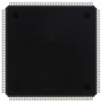
MCF5407AI220 Freescale Semiconductor, MCF5407AI220 Datasheet - Page 471

MCF5407AI220
Manufacturer Part Number
MCF5407AI220
Description
IC MPU 32B 220MHZ COLDF 208-FQFP
Manufacturer
Freescale Semiconductor
Series
MCF540xr
Specifications of MCF5407AI220
Core Processor
Coldfire V4
Core Size
32-Bit
Speed
220MHz
Connectivity
EBI/EMI, I²C, UART/USART
Peripherals
DMA, WDT
Number Of I /o
16
Program Memory Type
ROMless
Ram Size
4K x 8
Voltage - Supply (vcc/vdd)
1.65 V ~ 3.6 V
Oscillator Type
External
Operating Temperature
0°C ~ 70°C
Package / Case
208-FQFP
Maximum Clock Frequency
220 MHz
Operating Supply Voltage
1.8 V, 3.3 V
Maximum Operating Temperature
+ 105 C
Mounting Style
SMD/SMT
Minimum Operating Temperature
0 C
Program Memory Size
24KB
Cpu Speed
220MHz
Embedded Interface Type
I2C, UART
Digital Ic Case Style
FQFP
No. Of Pins
208
Supply Voltage Range
3.3V
Rohs Compliant
Yes
For Use With
M5407C3 - KIT EVAL FOR MCF5407 W/ETHERNET
Lead Free Status / RoHS Status
Lead free / RoHS Compliant
Eeprom Size
-
Program Memory Size
-
Data Converters
-
Lead Free Status / Rohs Status
Lead free / RoHS Compliant
Available stocks
Company
Part Number
Manufacturer
Quantity
Price
Company:
Part Number:
MCF5407AI220
Manufacturer:
freescaie
Quantity:
6
Company:
Part Number:
MCF5407AI220
Manufacturer:
Freescale Semiconductor
Quantity:
135
Company:
Part Number:
MCF5407AI220
Manufacturer:
FREESCALE
Quantity:
1 831
Company:
Part Number:
MCF5407AI220
Manufacturer:
Freescale Semiconductor
Quantity:
10 000
- Current page: 471 of 546
- Download datasheet (7Mb)
19.4.3 JTAG Boundary-Scan Register
The MCF5407 model includes an IEEE Standard 1149.1-compliant boundary-scan register
connected between TDI and TDO when the EXTEST or SAMPLE/PRELOAD instructions
are selected. This register captures signal data on the input pins, forces fixed values on the
output pins, and selects the direction and drive characteristics (a logic value or high
impedance) of the bidirectional and three-state pins. Table 19-4 shows MCF5407
boundary-scan register bits.
Bit
10
11
12
13
14
15
16
17
18
19
20
21
22
23
24
25
26
27
28
0
1
2
3
4
5
6
7
8
9
Cell Type
O.Pin
IO.Ctl
O.Pin
IO.Ctl
O.Pin
IO.Ctl
O.Pin
IO.Ctl
O.Pin
IO.Ctl
O.Pin
IO.Ctl
O.Pin
IO.Ctl
O.Pin
O.Pin
O.Pin
O.Pin
O.Pin
O.Pin
O.Ctl
I.Pin
I.Pin
I.Pin
I.Pin
I.Pin
I.Pin
I.Pin
I.Pin
PP0 enable
PP0
PP0
PP1 enable
PP1
PP1
PP2 enable
PP2
PP2
PP3 enable
PP3
PP3
PP4 enable
PP4
PP4
PP5 enable
PP5
PP5
PP6 enable
PP6
PP6
PP7 enable
PP7
PP7
PSTDDATA7
PSTDDATA6
PSTDDATA5
PSTDDATA4
PSTDDATA3
Pin Cell
Table 19-4. Boundary-Scan Bit Definitions
Chapter 19. IEEE 1149.1 Test Access Port (JTAG)
Pin Type
I/O
I/O
I/O
I/O
I/O
I/O
I/O
I/O
I/O
I/O
I/O
I/O
I/O
I/O
I/O
I/O
—
—
—
—
—
—
—
—
O
O
O
O
O
120
121
122
123
124
125
126
127
128
129
130
131
132
133
134
135
136
137
138
139
140
141
142
143
144
145
146
147
148
Bit
Cell Type
IO.Ctl
O.Pin
O.Pin
O.Pin
O.Pin
O.Pin
O.Pin
O.Pin
O.Pin
O.Pin
O.Pin
O.Pin
O.Pin
O.Pin
O.Pin
O.Pin
O.Pin
O.Pin
O.Pin
I.Pin
I.Pin
I.Pin
I.Pin
I.Pin
I.Pin
I.Pin
I.Pin
I.Pin
I.Pin
BE0
SCKE
SCAS
SRAS
DRAMW
CAS3
CAS2
CAS1
CAS0
RAS1
RAS0
TIN1
TIN0
TOUT0
TOUT1
BG
BD
BR
IRQ1
IRQ3
IRQ5
IRQ7
RSTI
TS
TS
TA enable
TA
TA
R/W
JTAG Register Descriptions
Pin Cell
Pin Type
I/O
I/O
I/O
I/O
I/O
—
O
O
O
O
O
O
O
O
O
O
O
O
O
O
O
I
I
I
I
I
I
I
I
19-7
Related parts for MCF5407AI220
Image
Part Number
Description
Manufacturer
Datasheet
Request
R
Part Number:
Description:
Mcf5407 Coldfire Integrated Microprocessor User
Manufacturer:
Freescale Semiconductor, Inc
Datasheet:
Part Number:
Description:
Manufacturer:
Freescale Semiconductor, Inc
Datasheet:
Part Number:
Description:
Manufacturer:
Freescale Semiconductor, Inc
Datasheet:
Part Number:
Description:
Manufacturer:
Freescale Semiconductor, Inc
Datasheet:
Part Number:
Description:
Manufacturer:
Freescale Semiconductor, Inc
Datasheet:
Part Number:
Description:
Manufacturer:
Freescale Semiconductor, Inc
Datasheet:
Part Number:
Description:
Manufacturer:
Freescale Semiconductor, Inc
Datasheet:
Part Number:
Description:
Manufacturer:
Freescale Semiconductor, Inc
Datasheet:
Part Number:
Description:
Manufacturer:
Freescale Semiconductor, Inc
Datasheet:
Part Number:
Description:
Manufacturer:
Freescale Semiconductor, Inc
Datasheet:
Part Number:
Description:
Manufacturer:
Freescale Semiconductor, Inc
Datasheet:
Part Number:
Description:
Manufacturer:
Freescale Semiconductor, Inc
Datasheet:
Part Number:
Description:
Manufacturer:
Freescale Semiconductor, Inc
Datasheet:
Part Number:
Description:
Manufacturer:
Freescale Semiconductor, Inc
Datasheet:
Part Number:
Description:
Manufacturer:
Freescale Semiconductor, Inc
Datasheet:


