MC9S08SH4CTG Freescale, MC9S08SH4CTG Datasheet - Page 60
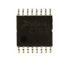
MC9S08SH4CTG
Manufacturer Part Number
MC9S08SH4CTG
Description
Manufacturer
Freescale
Datasheet
1.MC9S08SH4CTG.pdf
(338 pages)
Specifications of MC9S08SH4CTG
Cpu Family
HCS08
Device Core Size
8b
Frequency (max)
40MHz
Interface Type
I2C/SCI/SPI
Total Internal Ram Size
256Byte
# I/os (max)
13
Number Of Timers - General Purpose
1
Operating Supply Voltage (typ)
3.3/5V
Operating Supply Voltage (max)
5.5V
Operating Supply Voltage (min)
2.7V
On-chip Adc
8-chx10-bit
Instruction Set Architecture
CISC
Operating Temp Range
-40C to 85C
Operating Temperature Classification
Industrial
Mounting
Surface Mount
Pin Count
16
Package Type
TSSOP
Program Memory Type
Flash
Program Memory Size
4KB
Lead Free Status / RoHS Status
Compliant
Available stocks
Company
Part Number
Manufacturer
Quantity
Price
Company:

Part Number:
MC9S08SH4CTG
Manufacturer:
FREESCAL
Quantity:
96
Company:
Part Number:
MC9S08SH4CTG
Manufacturer:
Freescale
Quantity:
8 727


Chapter 5 Resets, Interrupts, and General System Control
5.4
The COP watchdog is intended to force a system reset when the application software fails to execute as
expected. To prevent a system reset from the COP timer (when it is enabled), application software must
reset the COP counter periodically. If the application program gets lost and fails to reset the COP counter
before it times out, a system reset is generated to force the system back to a known starting point.
After any reset, the COP watchdog is enabled (see
for additional information). If the COP watchdog is not used in an application, it can be disabled by
clearing COPT bits in SOPT1.
The COP counter is reset by writing 0x0055 and 0x00AA (in this order) to the address of SRS during the
selected timeout period. Writes do not affect the data in the read-only SRS. As soon as the write sequence
is done, the COP timeout period is restarted. If the program fails to do this during the time-out period, the
MCU will reset. Also, if any value other than 0x0055 or 0x00AA is written to SRS, the MCU is
immediately reset.
The COPCLKS bit in SOPT2 (see
information) selects the clock source used for the COP timer. The clock source options are either the bus
clock or an internal 1-kHz clock source. With each clock source, there are three associated time-outs
controlled by the COPT bits in SOPT1.
COPT bits. The COP watchdog defaults to operation from the 1-kHz clock source and the longest time-out
(2
When the bus clock source is selected, windowed COP operation is available by setting COPW in the
SOPT2 register. In this mode, writes to the SRS register to clear the COP timer must occur in the last 25%
of the selected timeout period. A premature write immediately resets the MCU. When the 1-kHz clock
source is selected, windowed COP operation is not available.
60
1
2
10
Windowed COP operation requires the user to clear the COP timer in the last 25% of the selected timeout period. This column
displays the minimun number of clock counts required before the COP timer can be reset hen in windowed COP mode
(COPW = 1).
Values shown in in miliseconds based on t
tolerance of this value.
COPCLKS
cycles).
N/A
0
0
0
1
1
1
Computer Operating Properly (COP) Watchdog
Control Bits
COPT[1:0]
0:0
0:1
1:0
1:1
0:1
1:0
1:1
MC9S08SH8 MCU Series Data Sheet, Rev. 3
Table 5-1. COP Configuration Options
Clock Source
Section 5.7.5, “System Options Register 2
LPO
1 kHz
1 kHz
1 kHz
Bus
Bus
Bus
N/A
Table 5-1
= 1 ms. See t
summaries the control functions of the COPCLKS and
COP Window
Section 5.7.4, “System Options Register 1
LPO
196,608 cycles
49,152 cycles
(COPW = 1)
6144 cycles
in the appendix
N/A
N/A
N/A
N/A
1
Opens
Section A.12.1, “Control
(SOPT2),” for additional
COP Overflow Count
2
2
2
10
8
5
COP is disabled
cycles (256 ms
cycles (32 ms
cycles (1.024 s
2
2
2
Freescale Semiconductor
13
16
18
cycles
cycles
cycles
Timing” for the
(SOPT1),”
2
1
1
)
)
)
Related parts for MC9S08SH4CTG
Image
Part Number
Description
Manufacturer
Datasheet
Request
R

Part Number:
Description:
TOWER ELEVATOR BOARDS HARDWARE
Manufacturer:
Freescale Semiconductor
Datasheet:

Part Number:
Description:
TOWER SERIAL I/O HARDWARE
Manufacturer:
Freescale Semiconductor
Datasheet:

Part Number:
Description:
LCD MODULE FOR TWR SYSTEM
Manufacturer:
Freescale Semiconductor
Datasheet:

Part Number:
Description:
DAUGHTER LCD WVGA I.MX51
Manufacturer:
Freescale Semiconductor
Datasheet:

Part Number:
Description:
TOWER SYSTEM BOARD MPC5125
Manufacturer:
Freescale Semiconductor
Datasheet:

Part Number:
Description:
KIT EVALUATION I.MX51
Manufacturer:
Freescale Semiconductor
Datasheet:

Part Number:
Description:
KIT DEVELOPMENT WINCE IMX25
Manufacturer:
Freescale Semiconductor
Datasheet:

Part Number:
Description:
TOWER SYSTEM KIT MPC5125
Manufacturer:
Freescale Semiconductor
Datasheet:

Part Number:
Description:
TOWER SYSTEM BOARD K40X256
Manufacturer:
Freescale Semiconductor
Datasheet:

Part Number:
Description:
TOWER SYSTEM KIT K40X256
Manufacturer:
Freescale Semiconductor
Datasheet:

Part Number:
Description:
Microcontrollers (MCU) MX28 PLATFORM DEV KIT
Manufacturer:
Freescale Semiconductor
Datasheet:

Part Number:
Description:
MCU, MPU & DSP Development Tools IAR KickStart Kit for Kinetis K60
Manufacturer:
Freescale Semiconductor
Datasheet:

Part Number:
Description:
24BIT HDMI MX535/08
Manufacturer:
Freescale Semiconductor
Datasheet:

Part Number:
Description:
Manufacturer:
Freescale Semiconductor, Inc
Datasheet:
Part Number:
Description:
Manufacturer:
Freescale Semiconductor, Inc
Datasheet: