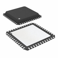
ATA6613P-PLPW Atmel, ATA6613P-PLPW Datasheet - Page 361

ATA6613P-PLPW
Manufacturer Part Number
ATA6613P-PLPW
Description
MCU W/LIN TXRX REG WTCHDG 48-QFN
Manufacturer
Atmel
Series
AVR® ATA66 LIN-SBCr
Datasheet
1.ATA6612-EK.pdf
(364 pages)
Specifications of ATA6613P-PLPW
Core Processor
AVR
Core Size
8-Bit
Speed
16MHz
Connectivity
I²C, LIN, SPI, UART/USART
Peripherals
Brown-out Detect/Reset, POR, PWM, WDT
Number Of I /o
23
Program Memory Size
16KB (16K x 8)
Program Memory Type
FLASH
Eeprom Size
512 x 8
Ram Size
1K x 8
Voltage - Supply (vcc/vdd)
2.7 V ~ 5.5 V
Data Converters
A/D 8x10b
Oscillator Type
Internal
Operating Temperature
-40°C ~ 125°C
Package / Case
48-QFN Exposed Pad
Processor Series
ATA6x
Core
AVR8
Data Bus Width
8 bit
Data Ram Size
1 KB
Interface Type
SPI, TWI, USART
Maximum Clock Frequency
16 MHz
Number Of Programmable I/os
23
Number Of Timers
3
Maximum Operating Temperature
+ 125 C
Mounting Style
SMD/SMT
Minimum Operating Temperature
- 40 C
On-chip Adc
10 bit, 8 Channel
Lead Free Status / RoHS Status
Lead free / RoHS Compliant
- Current page: 361 of 364
- Download datasheet (7Mb)
12. Revision History
9111H–AUTO–01/11
Please note that the following page numbers referred to in this section refer to the specific revision
mentioned, not to this document.
Revision No.
9111H-AUTO-01/11
9111G-AUTO-05/10
9111F-AUTO-12/08
9111E-AUTO-07/08
9111D-AUTO-06/08
9111C-AUTO-02/08
9111B-AUTO-11/07
History
15 changed
on page 357 changed
Off during Sleep Mode” on page 358 added
on page 45 changed
on page 357 added
Section 3.1 “Features” on page 5 changed
Section 3.3.3 “Ground Pin” on page 7 changed
Section 3.3.12 “Mode Input Pin (Mode)” on page 8 changed
Figure 3.2 “Modes of Operation” on page 10 changed
Section 3.3.20.4 “Fail-safe Mode” on page 13 changed
Section 3.3.23 “Voltage Regulator” on pages 16 to 17 changed
Section 6 “Electrical Characteristics” on pages 21 to 26 changed
Table 2-2 “Maximum Ratings of the SiP” on page 4 changed
Section 3.1 “Features” on page 5 changed
Section 3.2 “Description” on page 5 changed
Section 3.3.1 “Physical Layer Compatibility” on page 7 changed
Section 3.3.6 “Bus Pin LIN” on page 7 changed
Section 3.3.8 “TX Dominant Time-out Function” on page 8 changed
Section 3.3.10 “Enable Input Pin (EN)” on page 8 changed
Section 3.3.14 “KL_15 Pin” on page 9 changed
Section 3.3.20 “Modes of Operation” on pages 10 to 14 changed
Section 3.3.21 “Wake-up Scenarios from Silent to Sleep Mode on page
Section 3.3.23 “Voltage Regulator” on page 16 changed
Section 6 “Electrical Characteristics” on page 23 changed
Section 7.7.7.1 “Power Reduction Register” on page 66 changed
Section 11 “Errata” on page 360 changed
Table 2-2 “Maximum Ratings of the SiP” on page 4 changed
Section 4 “Absolute Maximum Ratings” on page 20 changed
Figure 8-1 “Typical LIN Slave Application” on page 355 changed
Figure 8-2 “Typical LIN Master Application” on page 356 changed
Figure 8-3 “LIN Slave Application with Minimum External Components”
Figure 8-4 “Typical LIN Master Application LIN Master Pull-up Switched
Figure 3-1 “Block Diagram” on page 6 changed
Section 3.3 “Functional Description” on pages 7 to 18 changed
Section 6.5.3.2 “The EEPROM Address Register – EEARH and EEARL”
Figure 8-2 “Typical LIN Master Application” on page 356 changed
Section 5 “Electrical Characteristics” on pages 21 to 26 changed
Section 6.6.6 “Calibrated Internal RC Oscillator” on page 57 changed
Figure 8-3 “LIN Slave Application with Minimum External Components
Atmel ATA6612/ATA6613
361
Related parts for ATA6613P-PLPW
Image
Part Number
Description
Manufacturer
Datasheet
Request
R

Part Number:
Description:
MCU W/LIN TXRX REG WTCHDG 48-QFN
Manufacturer:
Atmel
Datasheet:

Part Number:
Description:
Ata6613
Manufacturer:
ATMEL Corporation
Datasheet:

Part Number:
Description:
BOARD DEMO LIN-MCM FOR ATA6613
Manufacturer:
Atmel
Datasheet:

Part Number:
Description:
DEV KIT FOR AVR/AVR32
Manufacturer:
Atmel
Datasheet:

Part Number:
Description:
INTERVAL AND WIPE/WASH WIPER CONTROL IC WITH DELAY
Manufacturer:
ATMEL Corporation
Datasheet:

Part Number:
Description:
Low-Voltage Voice-Switched IC for Hands-Free Operation
Manufacturer:
ATMEL Corporation
Datasheet:

Part Number:
Description:
MONOLITHIC INTEGRATED FEATUREPHONE CIRCUIT
Manufacturer:
ATMEL Corporation
Datasheet:

Part Number:
Description:
AM-FM Receiver IC U4255BM-M
Manufacturer:
ATMEL Corporation
Datasheet:

Part Number:
Description:
Monolithic Integrated Feature Phone Circuit
Manufacturer:
ATMEL Corporation
Datasheet:

Part Number:
Description:
Multistandard Video-IF and Quasi Parallel Sound Processing
Manufacturer:
ATMEL Corporation
Datasheet:

Part Number:
Description:
High-performance EE PLD
Manufacturer:
ATMEL Corporation
Datasheet:

Part Number:
Description:
8-bit Flash Microcontroller
Manufacturer:
ATMEL Corporation
Datasheet:


