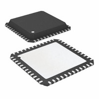
ATA6613P-PLPW Atmel, ATA6613P-PLPW Datasheet - Page 18

ATA6613P-PLPW
Manufacturer Part Number
ATA6613P-PLPW
Description
MCU W/LIN TXRX REG WTCHDG 48-QFN
Manufacturer
Atmel
Series
AVR® ATA66 LIN-SBCr
Datasheet
1.ATA6612-EK.pdf
(364 pages)
Specifications of ATA6613P-PLPW
Core Processor
AVR
Core Size
8-Bit
Speed
16MHz
Connectivity
I²C, LIN, SPI, UART/USART
Peripherals
Brown-out Detect/Reset, POR, PWM, WDT
Number Of I /o
23
Program Memory Size
16KB (16K x 8)
Program Memory Type
FLASH
Eeprom Size
512 x 8
Ram Size
1K x 8
Voltage - Supply (vcc/vdd)
2.7 V ~ 5.5 V
Data Converters
A/D 8x10b
Oscillator Type
Internal
Operating Temperature
-40°C ~ 125°C
Package / Case
48-QFN Exposed Pad
Processor Series
ATA6x
Core
AVR8
Data Bus Width
8 bit
Data Ram Size
1 KB
Interface Type
SPI, TWI, USART
Maximum Clock Frequency
16 MHz
Number Of Programmable I/os
23
Number Of Timers
3
Maximum Operating Temperature
+ 125 C
Mounting Style
SMD/SMT
Minimum Operating Temperature
- 40 C
On-chip Adc
10 bit, 8 Channel
Lead Free Status / RoHS Status
Lead free / RoHS Compliant
- Current page: 18 of 364
- Download datasheet (7Mb)
3.3.24
3.3.24.1
18
Atmel ATA6612/ATA6613
Watchdog
Typical Timing Sequence with R
The watchdog anticipates a trigger signal from the microcontroller at the NTRIG (negative
edge) input within a time window of T
t
NRES. After a watchdog reset the IC starts with the lead time. The timing basis of the watch-
dog is provided by the internal oscillator. Its time period, T
resistor R
During Silent or Sleep Mode the watchdog is switched off to reduce current consumption.
The minimum time for the first watchdog pulse is required after the undervoltage reset at
NRES disappears. It is defined as lead time t
lead time t
The trigger signal T
R
For example, with an external resistor of R
watchdog are as follows:
t
t
t
t
t
t
After ramping up the battery voltage, the 5V regulator is switched on. The reset output NRES
stays low for the time t
the trigger sequence from the microcontroller. The lead time, t
t
ger pulse NTRIG occurs during this time, the time t
occurs during the time t
t
nal from the microcontroller is anticipated within the time frame of t
triggering from glitches, the trigger pulse must be longer than t
serves to restart the watchdog sequence. If the triggering signal fails in this open window t
the NRES output will be drawn to ground. A triggering signal during the closed window t
immediately switches NRES to low.
trigmin
osc
OSC
d
1
2
nres
d
d
WD_OSC
= 7895
= 1053
= 1105
= 155ms. In this time, the first watchdog pulse from the microcontroller is required. If the trig-
= 155ms. The times t
= 0.405
= constant = 4ms
= 19.6µs due to 51k
> 200ns. If a triggering signal is not received, a reset signal will be generated at output
.
wd_osc
d
starts with the negative edge of the RXD output.
19.6µs = 20.6ms
19.6µs = 155ms
19.6µs = 21.6ms
R
(34k to 120k ).
WD_OSC
WD_OSC
wd
reset
– 0.0004
d
1
is adjustable between 20ms and 64ms using the external resistor
, a watchdog reset with t
= 51k
and t
(typically 4ms), then it switches to high, and the watchdog waits for
2
have a fixed relationship between each other. A triggering sig-
(R
WD_OSC
wd
. The trigger signal must exceed a minimum time
WD_OSC
)
2
d
. After wake up from Sleep or Silent Mode, the
(R
NRES
WD_OSC
= 51k ±1%, the typical parameters of the
1
= 4ms will reset the microcontroller after
starts immediately. If no trigger signal
in k ; t
osc
, is adjustable via the external
osc
TRIG,min
d
in µs)
2
, follows the reset and is
= 21.6ms. To avoid false
> 200ns. This slope
9111H–AUTO–01/11
2
1
,
Related parts for ATA6613P-PLPW
Image
Part Number
Description
Manufacturer
Datasheet
Request
R

Part Number:
Description:
MCU W/LIN TXRX REG WTCHDG 48-QFN
Manufacturer:
Atmel
Datasheet:

Part Number:
Description:
Ata6613
Manufacturer:
ATMEL Corporation
Datasheet:

Part Number:
Description:
BOARD DEMO LIN-MCM FOR ATA6613
Manufacturer:
Atmel
Datasheet:

Part Number:
Description:
DEV KIT FOR AVR/AVR32
Manufacturer:
Atmel
Datasheet:

Part Number:
Description:
INTERVAL AND WIPE/WASH WIPER CONTROL IC WITH DELAY
Manufacturer:
ATMEL Corporation
Datasheet:

Part Number:
Description:
Low-Voltage Voice-Switched IC for Hands-Free Operation
Manufacturer:
ATMEL Corporation
Datasheet:

Part Number:
Description:
MONOLITHIC INTEGRATED FEATUREPHONE CIRCUIT
Manufacturer:
ATMEL Corporation
Datasheet:

Part Number:
Description:
AM-FM Receiver IC U4255BM-M
Manufacturer:
ATMEL Corporation
Datasheet:

Part Number:
Description:
Monolithic Integrated Feature Phone Circuit
Manufacturer:
ATMEL Corporation
Datasheet:

Part Number:
Description:
Multistandard Video-IF and Quasi Parallel Sound Processing
Manufacturer:
ATMEL Corporation
Datasheet:

Part Number:
Description:
High-performance EE PLD
Manufacturer:
ATMEL Corporation
Datasheet:

Part Number:
Description:
8-bit Flash Microcontroller
Manufacturer:
ATMEL Corporation
Datasheet:


