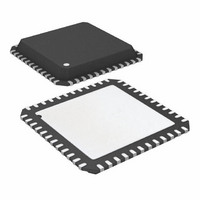
ATA6613P-PLPW Atmel, ATA6613P-PLPW Datasheet - Page 237

ATA6613P-PLPW
Manufacturer Part Number
ATA6613P-PLPW
Description
MCU W/LIN TXRX REG WTCHDG 48-QFN
Manufacturer
Atmel
Series
AVR® ATA66 LIN-SBCr
Datasheet
1.ATA6612-EK.pdf
(364 pages)
Specifications of ATA6613P-PLPW
Core Processor
AVR
Core Size
8-Bit
Speed
16MHz
Connectivity
I²C, LIN, SPI, UART/USART
Peripherals
Brown-out Detect/Reset, POR, PWM, WDT
Number Of I /o
23
Program Memory Size
16KB (16K x 8)
Program Memory Type
FLASH
Eeprom Size
512 x 8
Ram Size
1K x 8
Voltage - Supply (vcc/vdd)
2.7 V ~ 5.5 V
Data Converters
A/D 8x10b
Oscillator Type
Internal
Operating Temperature
-40°C ~ 125°C
Package / Case
48-QFN Exposed Pad
Processor Series
ATA6x
Core
AVR8
Data Bus Width
8 bit
Data Ram Size
1 KB
Interface Type
SPI, TWI, USART
Maximum Clock Frequency
16 MHz
Number Of Programmable I/os
23
Number Of Timers
3
Maximum Operating Temperature
+ 125 C
Mounting Style
SMD/SMT
Minimum Operating Temperature
- 40 C
On-chip Adc
10 bit, 8 Channel
Lead Free Status / RoHS Status
Lead free / RoHS Compliant
- Current page: 237 of 364
- Download datasheet (7Mb)
6.19.5.2
6.19.5.3
6.19.5.4
9111H–AUTO–01/11
Bit Rate Generator Unit
Bus Interface Unit
Address Match Unit
This unit controls the period of SCL when operating in a Master mode. The SCL period is con-
trolled by settings in the TWI Bit Rate Register (TWBR) and the Prescaler bits in the TWI
Status Register (TWSR). Slave operation does not depend on Bit Rate or Prescaler settings,
but the CPU clock frequency in the Slave must be at least 16 times higher than the SCL fre-
quency. Note that slaves may prolong the SCL low period, thereby reducing the average TWI
bus clock period. The SCL frequency is generated according to the following equation:
Note:
This unit contains the Data and Address Shift Register (TWDR), a START/STOP Controller
and Arbitration detection hardware. The TWDR contains the address or data bytes to be trans-
mitted, or the address or data bytes received. In addition to the 8-bit TWDR, the Bus Interface
Unit also contains a register containing the (N)ACK bit to be transmitted or received. This
(N)ACK Register is not directly accessible by the application software. However, when receiv-
ing, it can be set or cleared by manipulating the TWI Control Register (TWCR). When in
Transmitter mode, the value of the received (N)ACK bit can be determined by the value in the
TWSR.
The START/STOP Controller is responsible for generation and detection of START,
REPEATED START, and STOP conditions. The START/STOP controller is able to detect
START and STOP conditions even when the AVR
enabling the MCU to wake up if addressed by a Master.
If the TWI has initiated a transmission as Master, the Arbitration Detection hardware continu-
ously monitors the transmission trying to determine if arbitration is in process. If the TWI has
lost an arbitration, the Control Unit is informed. Correct action can then be taken and appropri-
ate status codes generated.
The Address Match unit checks if received address bytes match the seven-bit address in the
TWI Address Register (TWAR). If the TWI General Call Recognition Enable (TWGCE) bit in
the TWAR is written to one, all incoming address bits will also be compared against the Gen-
eral Call address. Upon an address match, the Control Unit is informed, allowing correct action
to be taken. The TWI may or may not acknowledge its address, depending on settings in the
TWCR. The Address Match unit is able to compare addresses even when the AVR
sleep mode, enabling the MCU to wake up if addressed by a Master. If another interrupt (e.g.,
INT0) occurs during TWI Power-down address match and wakes up the CPU, the TWI aborts
operation and return to it’s idle state. If this cause any problems, ensure that TWI Address
Match is the only enabled interrupt when entering Power-down.
SCL frequency
• TWBR = Value of the TWI Bit Rate Register.
• PrescalerValue = Value of the prescaler (see
TWBR should be 10 or higher if the TWI operates in Master mode. If TWBR is lower than 10, the
Master may produce an incorrect output on SDA and SCL for the reminder of the byte. The
problem occurs when operating the TWI in Master mode, sending Start + SLA + R/W to a Slave
(a Slave does not need to be connected to the bus for the condition to happen).
=
------------------------------------------------------------------------------------------- -
16
+
2(TWBR)
CPU Clock frequency
PrescalerValue
Atmel ATA6612/ATA6613
Table 6-88 on page
®
MCU is in one of the sleep modes,
240).
®
MCU is in
237
Related parts for ATA6613P-PLPW
Image
Part Number
Description
Manufacturer
Datasheet
Request
R

Part Number:
Description:
MCU W/LIN TXRX REG WTCHDG 48-QFN
Manufacturer:
Atmel
Datasheet:

Part Number:
Description:
Ata6613
Manufacturer:
ATMEL Corporation
Datasheet:

Part Number:
Description:
BOARD DEMO LIN-MCM FOR ATA6613
Manufacturer:
Atmel
Datasheet:

Part Number:
Description:
DEV KIT FOR AVR/AVR32
Manufacturer:
Atmel
Datasheet:

Part Number:
Description:
INTERVAL AND WIPE/WASH WIPER CONTROL IC WITH DELAY
Manufacturer:
ATMEL Corporation
Datasheet:

Part Number:
Description:
Low-Voltage Voice-Switched IC for Hands-Free Operation
Manufacturer:
ATMEL Corporation
Datasheet:

Part Number:
Description:
MONOLITHIC INTEGRATED FEATUREPHONE CIRCUIT
Manufacturer:
ATMEL Corporation
Datasheet:

Part Number:
Description:
AM-FM Receiver IC U4255BM-M
Manufacturer:
ATMEL Corporation
Datasheet:

Part Number:
Description:
Monolithic Integrated Feature Phone Circuit
Manufacturer:
ATMEL Corporation
Datasheet:

Part Number:
Description:
Multistandard Video-IF and Quasi Parallel Sound Processing
Manufacturer:
ATMEL Corporation
Datasheet:

Part Number:
Description:
High-performance EE PLD
Manufacturer:
ATMEL Corporation
Datasheet:

Part Number:
Description:
8-bit Flash Microcontroller
Manufacturer:
ATMEL Corporation
Datasheet:


