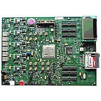
HW-V5-ML550-UNI-G Xilinx Inc, HW-V5-ML550-UNI-G Datasheet - Page 70

HW-V5-ML550-UNI-G
Manufacturer Part Number
HW-V5-ML550-UNI-G
Description
EVALUATION PLATFORM VIRTEX-5
Manufacturer
Xilinx Inc
Series
Virtex™-5 LXTr
Type
FPGAr
Datasheet
1.HW-V5-ML550-UNI-G.pdf
(88 pages)
Specifications of HW-V5-ML550-UNI-G
Contents
Development Platform, Power Supply, Loopback Board, CompactFlash Card, software and documentation
Silicon Manufacturer
Xilinx
Features
64M X 8 DDR SDRAM Memory, Six Samtec LVDS Connectors
Kit Contents
Board, Cable, PSU, CD, Docs
Silicon Family Name
Virtex-5
Silicon Core Number
XC5VLX50T-FFG1136
Rohs Compliant
Yes
Lead Free Status / RoHS Status
Lead free / RoHS Compliant
For Use With/related Products
Virtex™-5 LXT
Lead Free Status / RoHS Status
Lead free / RoHS Compliant, Lead free / RoHS Compliant
Available stocks
Company
Part Number
Manufacturer
Quantity
Price
Appendix C: LCD Interface
Table C-3: KS0713 Pin Connections
70
LCD Control Pins
Connector J1 Connector J2
16
15
14
13
12
11
10
9
8
7
6
5
4
3
1
2
Controller – LCD Panel Connections
16
15
14
13
12
11
10
9
8
7
6
5
4
3
1
2
The controller die, KS0713, connects to the LCD glass panel and user connection pins via a
small PCB. Other necessary pins have default connections on the PCB.
how all pins of the die are connected. The pins in
PCB, and the other pins connect to the user-accessible connectors.
Connection
PCB
10
11
12
13
14
15
16
17
1
2
3
4
5
6
7
8
9
Connected to
www.xilinx.com
VDD
VDD
VDD
VDD
VDD
VDD
VDD
VSS
VSS
RW_WR
RESETB
DUTY0
DUTY1
TEMPS
Signal
INTRS
Name
E_RD
HPM
CS1B
VDD
BSTS
DB0
DB1
DB2
DB3
DB4
DB5
DB6
DB7
CLS
VSS
CS2
MS
RS
MI
PS
blue
ML550 Networking Interfaces Platform
Chip enable is active Low
Initialize the LCD
Register select
Read/Write
Enable/Read
8-bit bidirectional data bus.
In serial mode DB0-DB5 are High
impedance, DB6 is the serial clock
input, and DB7 is the serial data
input.
Processor mode select
Parallel or Serial
Ground
Power Supply
Active High chip enable.
LCD driver duty ratio. Set to 1/65
Master / Slave operation. Set to
Master
Built-in oscillator enable
Set to -0.05%/ C
Internal resistors used
Normal mode set
Voltage converter input is VDD
(2.4<VDD<3.6)
connect to default values on the
UG202 (v1.4) April 18, 2008
Description
Table C-3
shows
R


