HW-V5-ML550-UNI-G Xilinx Inc, HW-V5-ML550-UNI-G Datasheet - Page 17
HW-V5-ML550-UNI-G
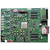
Manufacturer Part Number
HW-V5-ML550-UNI-G
Description
EVALUATION PLATFORM VIRTEX-5
Manufacturer
Xilinx Inc
Series
Virtex™-5 LXTr
Type
FPGAr
Datasheet
1.HW-V5-ML550-UNI-G.pdf
(88 pages)
Specifications of HW-V5-ML550-UNI-G
Contents
Development Platform, Power Supply, Loopback Board, CompactFlash Card, software and documentation
Silicon Manufacturer
Xilinx
Features
64M X 8 DDR SDRAM Memory, Six Samtec LVDS Connectors
Kit Contents
Board, Cable, PSU, CD, Docs
Silicon Family Name
Virtex-5
Silicon Core Number
XC5VLX50T-FFG1136
Rohs Compliant
Yes
Lead Free Status / RoHS Status
Lead free / RoHS Compliant
For Use With/related Products
Virtex™-5 LXT
Lead Free Status / RoHS Status
Lead free / RoHS Compliant, Lead free / RoHS Compliant
Available stocks
Company
Part Number
Manufacturer
Quantity
Price


ML550 Networking Interfaces Platform
UG202 (v1.4) April 18, 2008
ML550 Board Startup and Operation
R
BERT GUI Tcl Interface Installation
1.
2.
3.
The BERT GUI is now ready to use.
1.
2.
3.
4.
5.
6.
7.
8.
9.
Locate executable file ActiveTcl8.4.7.0-win32-ix86-108887.exe in
C:\ML550 BERT REV1.x and double-click on it.
The Active State Active Tcl installer opens. Follow the dialog and accept the defaults.
At the end of the process, the installer reports the folders created during the install.
Click Finish.
Create a GUI shortcut for the Windows desktop:
a.
b. Right-click on this file and choose Create shortcut.
c.
Turn OFF the ML550 power.
Install either the LVDS Loopback board across the six LVDS Samtec connectors (if not
already installed), or install a single Blue Ribbon cable between the center TX and RX
Samtec connectors, P46 and P6 respectively.
Install the Compact Flash card into the J21 socket (if not already installed).
Confirm that the flash card image select rotary switch SW9 is set to position 0.
The CLOCK MOD 1 & 2 parallel programming DIP switches default to all OFF and can
be safely ignored.
The BERT test uses Clock Module 2 / U19. The GUI sets the Clock Module 2 / U19
initial frequency to 400 MHz.
Turn ON the ML550 power. The DONE LED D19 should come on.
On the PC, double-click on the gui_rev1.x.exe shortcut. The BERT GUI launches.
At the upper left are two selection boxes. The upper chooses the COM port, the lower
chooses the test type. Click on the upper and select COM4. Click on the lower and
select PRBS15.
Click on the big Start/Restart button.
If the COM port is correct, the test begins.
If the COM port is not correct, the GUI most likely will hang. If this occurs, close and
relaunch the application. When repeating the selection sequence, choose COM3. If this
also fails, repeat this procedure choosing a lower COM port number each time
through.
Some computers have more than four COM ports. It is possible that the USB-to-COM
bridge driver will select a COM port that the GUI will not communicate with (e.g.,
COM14.) The workaround in this instance is to go to:
Control Panel -> System -> Hardware -> Device Manager -> Ports
Identify the port selected by the CP210x USB to UART driver. If the COM port is not
COM1, COM2, COM3, or COM4, change the port using this path:
Control Panel -> System -> Hardware -> Device Manager -> Ports -> CP210x USB
to UART-> Port Settings -> Advanced COM Port Number
Locate executable file gui_rev1.x.exe in
C:\ML550 BERT REV1.x\GUI_Rev1.x.
Drag the shortcut to the Windows XP desktop.
www.xilinx.com
Quick Start Guide
17
Related parts for HW-V5-ML550-UNI-G
Image
Part Number
Description
Manufacturer
Datasheet
Request
R

Part Number:
Description:
IC CPLD .8K 36MCELL 44-VQFP
Manufacturer:
Xilinx Inc
Datasheet:

Part Number:
Description:
IC CPLD 72MCRCELL 10NS 44VQFP
Manufacturer:
Xilinx Inc
Datasheet:

Part Number:
Description:
IC CPLD 1.6K 72MCELL 64-VQFP
Manufacturer:
Xilinx Inc
Datasheet:

Part Number:
Description:
IC CR-II CPLD 64MCELL 44-VQFP
Manufacturer:
Xilinx Inc
Datasheet:

Part Number:
Description:
IC CPLD 1.6K 72MCELL 100-TQFP
Manufacturer:
Xilinx Inc
Datasheet:

Part Number:
Description:
IC CR-II CPLD 64MCELL 56-BGA
Manufacturer:
Xilinx Inc
Datasheet:

Part Number:
Description:
IC CPLD 72MCRCELL 7.5NS 44VQFP
Manufacturer:
Xilinx Inc
Datasheet:
Part Number:
Description:
IC CR-II CPLD 64MCELL 100-VQFP
Manufacturer:
Xilinx Inc
Datasheet:
Part Number:
Description:
IC CPLD 1.6K 72MCELL 100-TQFP
Manufacturer:
Xilinx Inc
Datasheet:

Part Number:
Description:
IC CPLD 72MCRCELL 7.5NS 64VQFP
Manufacturer:
Xilinx Inc
Datasheet:
Part Number:
Description:
IC CPLD 1.6K 72MCELL 100-TQFP
Manufacturer:
Xilinx Inc
Datasheet:

Part Number:
Description:
IC CPLD 1.5K 64MCELL HP 44-VQFP
Manufacturer:
Xilinx Inc

Part Number:
Description:
IC CPLD 36MCRCELL 15NS 44PLCC
Manufacturer:
Xilinx Inc
Datasheet:

Part Number:
Description:
IC CPLD 36MCRCELL 10NS 44PLCC
Manufacturer:
Xilinx Inc
Datasheet:

Part Number:
Description:
IC CPLD 1.5K 64MCELL HP 44-VQFP
Manufacturer:
Xilinx Inc