C8051F996DK Silicon Laboratories Inc, C8051F996DK Datasheet - Page 288
C8051F996DK
Manufacturer Part Number
C8051F996DK
Description
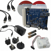
KIT DEV FOR C8051F996
Manufacturer
Silicon Laboratories Inc
Type
MCUr
Datasheets
1.C8051F996DK.pdf
(24 pages)
2.C8051F996DK.pdf
(2 pages)
3.C8051F996DK.pdf
(4 pages)
4.C8051F996DK.pdf
(322 pages)
Specifications of C8051F996DK
Contents
Board, Batteries, Cables, CDs, Debug Adapter, Documentation, Power Adapter
Processor To Be Evaluated
C8051F996
Processor Series
C8051F98x
Interface Type
USB
Operating Supply Voltage
3 V
Lead Free Status / RoHS Status
Lead free / RoHS Compliant
For Use With/related Products
C8051F996
Lead Free Status / Rohs Status
Lead free / RoHS Compliant
Other names
336-1963


C8051F99x-C8051F98x
25.2.3. Comparator 0/SmaRTClock Capture Mode
The Capture Mode in Timer 2 allows either Comparator 0 or the SmaRTClock period to be measured
against the system clock or the system clock divided by 12. Comparator 0 and the SmaRTClock period can
also be compared against each other. Timer 2 Capture Mode is enabled by setting TF2CEN to 1. Timer 2
should be in 16-bit auto-reload mode when using Capture Mode.
When Capture Mode is enabled, a capture event will be generated either every Comparator 0 rising edge
or every 8 SmaRTClock clock cycles, depending on the T2XCLK1 setting. When the capture event occurs,
the
(TMR2RLH:TMR2RLL) and the TF2H flag is set (triggering an interrupt if Timer 2 interrupts are enabled).
By recording the difference between two successive timer capture values, the Comparator 0 or SmaRT-
Clock period can be determined with respect to the Timer 2 clock. The Timer 2 clock should be much faster
than the capture clock to achieve an accurate reading.
For example, if T2ML = 1b, T2XCLK1 = 0b, and TF2CEN = 1b, Timer 2 will clock every SYSCLK and cap-
ture every SmaRTClock clock divided by 8. If the SYSCLK is 24.5 MHz and the difference between two
successive captures is 5984, then the SmaRTClock clock is as follows:
24.5 MHz/(5984/8) = 0.032754 MHz or 32.754 kHz.
This mode allows software to determine the exact SmaRTClock frequency in self-oscillate mode and the
time between consecutive Comparator 0 rising edges, which is useful for detecting changes in the capaci-
tance of a Touch Sense Switch.
288
SmaRTClock / 8
SmaRTClock / 8
contents
Comparator 0
SYSCLK / 12
Comparator 0
SYSCLK
of
T2XCLK[1:0]
T2XCLK1
Timer
X0
01
11
0
1
Figure 25.6. Timer 2 Capture Mode Block Diagram
M
T
H
3
2
M
T
3
L
CKCON
M
T
H
2
(TMR2H:TMR2L)
M
T
0
1
2
L
M
T
1
M
T
0
S
C
A
1
TF2CEN
S
C
A
0
TR2
Rev. 1.0
Capture
are
TCLK
loaded
TMR2RLL TMR2RLH
TMR2L
into
TMR2H
the
Timer 2
T2XCLK1
T2XCLK0
TF2CEN
T2SPLIT
TF2LEN
TF2H
TF2L
TR2
reload
registers
Interrupt
Related parts for C8051F996DK
Image
Part Number
Description
Manufacturer
Datasheet
Request
R

Part Number:
Description:
SMD/C°/SINGLE-ENDED OUTPUT SILICON OSCILLATOR
Manufacturer:
Silicon Laboratories Inc
Part Number:
Description:
Manufacturer:
Silicon Laboratories Inc
Datasheet:
Part Number:
Description:
N/A N/A/SI4010 AES KEYFOB DEMO WITH LCD RX
Manufacturer:
Silicon Laboratories Inc
Datasheet:
Part Number:
Description:
N/A N/A/SI4010 SIMPLIFIED KEY FOB DEMO WITH LED RX
Manufacturer:
Silicon Laboratories Inc
Datasheet:
Part Number:
Description:
N/A/-40 TO 85 OC/EZLINK MODULE; F930/4432 HIGH BAND (REV E/B1)
Manufacturer:
Silicon Laboratories Inc
Part Number:
Description:
EZLink Module; F930/4432 Low Band (rev e/B1)
Manufacturer:
Silicon Laboratories Inc
Part Number:
Description:
I°/4460 10 DBM RADIO TEST CARD 434 MHZ
Manufacturer:
Silicon Laboratories Inc
Part Number:
Description:
I°/4461 14 DBM RADIO TEST CARD 868 MHZ
Manufacturer:
Silicon Laboratories Inc
Part Number:
Description:
I°/4463 20 DBM RFSWITCH RADIO TEST CARD 460 MHZ
Manufacturer:
Silicon Laboratories Inc
Part Number:
Description:
I°/4463 20 DBM RADIO TEST CARD 868 MHZ
Manufacturer:
Silicon Laboratories Inc
Part Number:
Description:
I°/4463 27 DBM RADIO TEST CARD 868 MHZ
Manufacturer:
Silicon Laboratories Inc
Part Number:
Description:
I°/4463 SKYWORKS 30 DBM RADIO TEST CARD 915 MHZ
Manufacturer:
Silicon Laboratories Inc
Part Number:
Description:
N/A N/A/-40 TO 85 OC/4463 RFMD 30 DBM RADIO TEST CARD 915 MHZ
Manufacturer:
Silicon Laboratories Inc
Part Number:
Description:
I°/4463 20 DBM RADIO TEST CARD 169 MHZ
Manufacturer:
Silicon Laboratories Inc