C8051F996DK Silicon Laboratories Inc, C8051F996DK Datasheet - Page 11
C8051F996DK
Manufacturer Part Number
C8051F996DK
Description
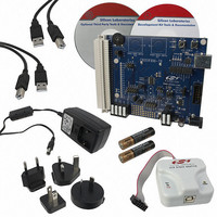
KIT DEV FOR C8051F996
Manufacturer
Silicon Laboratories Inc
Type
MCUr
Datasheets
1.C8051F996DK.pdf
(24 pages)
2.C8051F996DK.pdf
(2 pages)
3.C8051F996DK.pdf
(4 pages)
4.C8051F996DK.pdf
(322 pages)
Specifications of C8051F996DK
Contents
Board, Batteries, Cables, CDs, Debug Adapter, Documentation, Power Adapter
Processor To Be Evaluated
C8051F996
Processor Series
C8051F98x
Interface Type
USB
Operating Supply Voltage
3 V
Lead Free Status / RoHS Status
Lead free / RoHS Compliant
For Use With/related Products
C8051F996
Lead Free Status / Rohs Status
Lead free / RoHS Compliant
Other names
336-1963


C8051F99x-C8051F98x
List of Tables
Table 2.1. Product Selection Guide . . . . . . . . . . . . . . . . . . . . . . . . . . . . . . . . . . . . . 31
Table 3.1. Pin Definitions for the C8051F99x-C8051F98x . . . . . . . . . . . . . . . . . . . 32
Table 3.2. QFN-20 Package Dimensions . . . . . . . . . . . . . . . . . . . . . . . . . . . . . . . . 38
Table 3.3. PCB Land Pattern . . . . . . . . . . . . . . . . . . . . . . . . . . . . . . . . . . . . . . . . . . 40
Table 3.4. QFN-24 Package Dimensions . . . . . . . . . . . . . . . . . . . . . . . . . . . . . . . . 41
Table 3.5. PCB Land Pattern . . . . . . . . . . . . . . . . . . . . . . . . . . . . . . . . . . . . . . . . . . 43
Table 3.6. QSOP-24 Package Dimensions . . . . . . . . . . . . . . . . . . . . . . . . . . . . . . . 44
Table 3.7. PCB Land Pattern . . . . . . . . . . . . . . . . . . . . . . . . . . . . . . . . . . . . . . . . . . 45
Table 4.1. Absolute Maximum Ratings .................................................................... 46
Table 4.2. Global Electrical Characteristics ............................................................. 47
Table 4.3. Port I/O DC Electrical Characteristics ..................................................... 52
Table 4.4. Reset Electrical Characteristics .............................................................. 55
Table 4.5. Power Management Electrical Specifications ......................................... 56
Table 4.6. Flash Electrical Characteristics .............................................................. 56
Table 4.7. Internal Precision Oscillator Electrical Characteristics ........................... 56
Table 4.8. Internal Low-Power Oscillator Electrical Characteristics ........................ 56
Table 4.9. SmaRTClock Characteristics .................................................................. 57
Table 4.10. ADC0 Electrical Characteristics ............................................................ 57
Table 4.11. Temperature Sensor Electrical Characteristics .................................... 58
Table 4.12. Voltage Reference Electrical Characteristics ....................................... 59
Table 4.13. IREF0 Electrical Characteristics ........................................................... 60
Table 4.14. Comparator Electrical Characteristics .................................................. 61
Table 4.15. VREG0 Electrical Characteristics ......................................................... 62
Table 4.16. Capacitive Sense Electrical Characteristics ......................................... 63
Table 5.1. Representative Conversion Times and Energy Consumption for the SAR
ADC with 1.65 V High-Speed VREF . . . . . . . . . . . . . . . . . . . . . . . . . . . 71
Table 8.1. Operation with Auto-scan and Accumulate . . . . . . . . . . . . . . . . . . . . . 103
Table 9.1. CIP-51 Instruction Set Summary . . . . . . . . . . . . . . . . . . . . . . . . . . . . . 120
Table 12.1. Special Function Register (SFR) Memory Map (Page 0x0) . . . . . . . . 131
Table 12.2. Special Function Register (SFR) Memory Map (Page 0xF) . . . . . . . . 132
Table 12.3. Special Function Registers . . . . . . . . . . . . . . . . . . . . . . . . . . . . . . . . . 133
Table 13.1. Interrupt Summary . . . . . . . . . . . . . . . . . . . . . . . . . . . . . . . . . . . . . . . 139
Table 14.1. Flash Security Summary . . . . . . . . . . . . . . . . . . . . . . . . . . . . . . . . . . 152
Table 15.1. Power Modes . . . . . . . . . . . . . . . . . . . . . . . . . . . . . . . . . . . . . . . . . . . 161
Table 16.1. Example 16-bit CRC Outputs . . . . . . . . . . . . . . . . . . . . . . . . . . . . . . . 171
Table 19.1. Recommended XFCN Settings for Crystal Mode . . . . . . . . . . . . . . . . 188
Table 19.2. Recommended XFCN Settings for RC and C modes . . . . . . . . . . . . . 189
Table 20.1. SmaRTClock Internal Registers ......................................................... 196
Table 20.2. SmaRTClock Load Capacitance Settings . . . . . . . . . . . . . . . . . . . . . 203
Table 20.3. SmaRTClock Bias Settings . . . . . . . . . . . . . . . . . . . . . . . . . . . . . . . . 205
Table 21.1. Port I/O Assignment for Analog Functions . . . . . . . . . . . . . . . . . . . . . 215
Table 21.2. Port I/O Assignment for Digital Functions . . . . . . . . . . . . . . . . . . . . . . 216
Table 21.3. Port I/O Assignment for External Digital Event Capture Functions . . 216
Rev. 1.0
11
Related parts for C8051F996DK
Image
Part Number
Description
Manufacturer
Datasheet
Request
R

Part Number:
Description:
SMD/C°/SINGLE-ENDED OUTPUT SILICON OSCILLATOR
Manufacturer:
Silicon Laboratories Inc
Part Number:
Description:
Manufacturer:
Silicon Laboratories Inc
Datasheet:
Part Number:
Description:
N/A N/A/SI4010 AES KEYFOB DEMO WITH LCD RX
Manufacturer:
Silicon Laboratories Inc
Datasheet:
Part Number:
Description:
N/A N/A/SI4010 SIMPLIFIED KEY FOB DEMO WITH LED RX
Manufacturer:
Silicon Laboratories Inc
Datasheet:
Part Number:
Description:
N/A/-40 TO 85 OC/EZLINK MODULE; F930/4432 HIGH BAND (REV E/B1)
Manufacturer:
Silicon Laboratories Inc
Part Number:
Description:
EZLink Module; F930/4432 Low Band (rev e/B1)
Manufacturer:
Silicon Laboratories Inc
Part Number:
Description:
I°/4460 10 DBM RADIO TEST CARD 434 MHZ
Manufacturer:
Silicon Laboratories Inc
Part Number:
Description:
I°/4461 14 DBM RADIO TEST CARD 868 MHZ
Manufacturer:
Silicon Laboratories Inc
Part Number:
Description:
I°/4463 20 DBM RFSWITCH RADIO TEST CARD 460 MHZ
Manufacturer:
Silicon Laboratories Inc
Part Number:
Description:
I°/4463 20 DBM RADIO TEST CARD 868 MHZ
Manufacturer:
Silicon Laboratories Inc
Part Number:
Description:
I°/4463 27 DBM RADIO TEST CARD 868 MHZ
Manufacturer:
Silicon Laboratories Inc
Part Number:
Description:
I°/4463 SKYWORKS 30 DBM RADIO TEST CARD 915 MHZ
Manufacturer:
Silicon Laboratories Inc
Part Number:
Description:
N/A N/A/-40 TO 85 OC/4463 RFMD 30 DBM RADIO TEST CARD 915 MHZ
Manufacturer:
Silicon Laboratories Inc
Part Number:
Description:
I°/4463 20 DBM RADIO TEST CARD 169 MHZ
Manufacturer:
Silicon Laboratories Inc