C8051F996DK Silicon Laboratories Inc, C8051F996DK Datasheet - Page 187
C8051F996DK
Manufacturer Part Number
C8051F996DK
Description
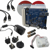
KIT DEV FOR C8051F996
Manufacturer
Silicon Laboratories Inc
Type
MCUr
Datasheets
1.C8051F996DK.pdf
(24 pages)
2.C8051F996DK.pdf
(2 pages)
3.C8051F996DK.pdf
(4 pages)
4.C8051F996DK.pdf
(322 pages)
Specifications of C8051F996DK
Contents
Board, Batteries, Cables, CDs, Debug Adapter, Documentation, Power Adapter
Processor To Be Evaluated
C8051F996
Processor Series
C8051F98x
Interface Type
USB
Operating Supply Voltage
3 V
Lead Free Status / RoHS Status
Lead free / RoHS Compliant
For Use With/related Products
C8051F996
Lead Free Status / Rohs Status
Lead free / RoHS Compliant
Other names
336-1963


C8051F99x-C8051F98x
19.1. Programmable Precision Internal Oscillator
All C8051F99x-C8051F98x devices include a programmable precision internal oscillator that may be
selected as the system clock. OSCICL is factory calibrated to obtain a 24.5 MHz frequency. See Section
“4. Electrical Characteristics” on page 46 for complete oscillator specifications.
The precision oscillator supports a spread spectrum mode which modulates the output frequency in order
to reduce the EMI generated by the system. When enabled (SSE = 1), the oscillator output frequency is
modulated by a stepped triangle wave whose frequency is equal to the oscillator frequency divided by 384
(63.8 kHz using the factory calibration). The deviation from the nominal oscillator frequency is +0%, –1.6%,
and the step size is typically 0.26% of the nominal frequency. When using this mode, the typical average
oscillator frequency is lowered from 24.5 MHz to 24.3 MHz.
19.2. Low Power Internal Oscillator
All C8051F99x-C8051F98x devices include a low power internal oscillator that defaults as the system
clock after a system reset. The low power internal oscillator frequency is 20 MHz ± 10% and is automati-
cally enabled when selected as the system clock and disabled when not in use. See Section “4. Electrical
Characteristics” on page 46 for complete oscillator specifications.
19.3. External Oscillator Drive Circuit
All C8051F99x-C8051F98x devices include an external oscillator circuit that may drive an external crystal,
ceramic resonator, capacitor, or RC network. A CMOS clock may also provide a clock input. Figure 19.1
shows a block diagram of the four external oscillator options. The external oscillator is enabled and config-
ured using the OSCXCN register.
The external oscillator output may be selected as the system clock or used to clock some of the digital
peripherals (e.g., Timers, PCA, etc.). See the data sheet chapters for each digital peripheral for details.
See Section “4. Electrical Characteristics” on page 46 for complete oscillator specifications.
19.3.1. External Crystal Mode
If a crystal or ceramic resonator is used as the external oscillator, the crystal/resonator and a 10 Mresis-
tor must be wired across the XTAL1 and XTAL2 pins as shown in Figure 19.1, Option 1. Appropriate load-
ing capacitors should be added to XTAL1 and XTAL2, and both pins should be configured for analog I/O
with the digital output drivers disabled.
Figure 19.2 shows the external oscillator circuit for a 20 MHz quartz crystal with a manufacturer recom-
mended load capacitance of 12.5 pF. Loading capacitors are "in series" as seen by the crystal and "in par-
allel" with the stray capacitance of the XTAL1 and XTAL2 pins. The total value of the each loading
capacitor and the stray capacitance of each XTAL pin should equal 12.5 pF x 2 = 25 pF. With a stray
capacitance of 10 pF per pin, the 15 pF capacitors yield an equivalent series capacitance of 12.5 pF
across the crystal.
Note: The recommended load capacitance depends upon the crystal and the manufacturer. Please refer to the crystal
data sheet when completing these calculations.
Rev. 1.0
187
Related parts for C8051F996DK
Image
Part Number
Description
Manufacturer
Datasheet
Request
R

Part Number:
Description:
SMD/C°/SINGLE-ENDED OUTPUT SILICON OSCILLATOR
Manufacturer:
Silicon Laboratories Inc
Part Number:
Description:
Manufacturer:
Silicon Laboratories Inc
Datasheet:
Part Number:
Description:
N/A N/A/SI4010 AES KEYFOB DEMO WITH LCD RX
Manufacturer:
Silicon Laboratories Inc
Datasheet:
Part Number:
Description:
N/A N/A/SI4010 SIMPLIFIED KEY FOB DEMO WITH LED RX
Manufacturer:
Silicon Laboratories Inc
Datasheet:
Part Number:
Description:
N/A/-40 TO 85 OC/EZLINK MODULE; F930/4432 HIGH BAND (REV E/B1)
Manufacturer:
Silicon Laboratories Inc
Part Number:
Description:
EZLink Module; F930/4432 Low Band (rev e/B1)
Manufacturer:
Silicon Laboratories Inc
Part Number:
Description:
I°/4460 10 DBM RADIO TEST CARD 434 MHZ
Manufacturer:
Silicon Laboratories Inc
Part Number:
Description:
I°/4461 14 DBM RADIO TEST CARD 868 MHZ
Manufacturer:
Silicon Laboratories Inc
Part Number:
Description:
I°/4463 20 DBM RFSWITCH RADIO TEST CARD 460 MHZ
Manufacturer:
Silicon Laboratories Inc
Part Number:
Description:
I°/4463 20 DBM RADIO TEST CARD 868 MHZ
Manufacturer:
Silicon Laboratories Inc
Part Number:
Description:
I°/4463 27 DBM RADIO TEST CARD 868 MHZ
Manufacturer:
Silicon Laboratories Inc
Part Number:
Description:
I°/4463 SKYWORKS 30 DBM RADIO TEST CARD 915 MHZ
Manufacturer:
Silicon Laboratories Inc
Part Number:
Description:
N/A N/A/-40 TO 85 OC/4463 RFMD 30 DBM RADIO TEST CARD 915 MHZ
Manufacturer:
Silicon Laboratories Inc
Part Number:
Description:
I°/4463 20 DBM RADIO TEST CARD 169 MHZ
Manufacturer:
Silicon Laboratories Inc