PCM18XK1 Microchip Technology, PCM18XK1 Datasheet - Page 88
PCM18XK1
Manufacturer Part Number
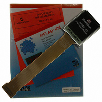
PCM18XK1
Description
MODULE PROC PIC18F8680,6680,8565
Manufacturer
Microchip Technology
Datasheet
1.PCM18XK1.pdf
(496 pages)
Specifications of PCM18XK1
Accessory Type
Processor Module
Lead Free Status / RoHS Status
Not applicable / Not applicable
For Use With/related Products
ICE2000
For Use With
ICE2000 - EMULATOR MPLAB-ICE 2000 POD
Lead Free Status / Rohs Status
Lead free / RoHS Compliant


PIC18F6585/8585/6680/8680
5.2.2
The Table Latch (TABLAT) is an 8-bit register mapped
into the SFR space. The Table Latch is used to hold 8-
bit data during data transfers between program
memory and data RAM.
5.2.3
The Table Pointer (TBLPTR) addresses a byte within
the program memory. The TBLPTR is comprised of
three SFR registers: Table Pointer Upper Byte, Table
Pointer High Byte and Table Pointer Low Byte
(TBLPTRU:TBLPTRH:TBLPTRL). These three regis-
ters join to form a 22-bit wide pointer. The low-order
21 bits allow the device to address up to 2 Mbytes of
program memory space. The 22nd bit allows access to
the device ID, the user ID and the configuration bits.
The Table Pointer, TBLPTR, is used by the TBLRD and
TBLWT instructions. These instructions can update the
TBLPTR in one of four ways based on the table opera-
tion. These operations are shown in Table 5-1. These
operations on the TBLPTR only affect the low-order
21 bits.
TABLE 5-1:
FIGURE 5-3:
DS30491C-page 86
TBLRD*
TBLWT*
TBLRD*+
TBLWT*+
TBLRD*-
TBLWT*-
TBLRD+*
TBLWT+*
Example
21
TABLAT – TABLE LATCH REGISTER
TBLPTR – TABLE POINTER
REGISTER
TABLE POINTER OPERATIONS WITH TBLRD AND TBLWT INSTRUCTIONS
TBLPTRU
TABLE POINTER BOUNDARIES BASED ON OPERATION
16
ERASE – TBLPTR<20:6>
15
TBLPTR is incremented before the read/write
TBLPTR is decremented after the read/write
TBLPTR is incremented after the read/write
WRITE – TBLPTR<21:3>
TBLPTRH
Operation on Table Pointer
READ – TBLPTR<21:0>
TBLPTR is not modified
5.2.4
TBLPTR is used in reads, writes and erases of the
Flash program memory.
When a TBLRD is executed, all 22 bits of the table
pointer determine which byte is read from program
memory into TABLAT.
When a TBLWT is executed, the three LSbs of the Table
Pointer (TBLPTR<2:0>) determine which of the eight
program memory holding registers is written to. When
the timed write to program memory (long write) begins,
the 19 MSbs of the Table Pointer (TBLPTR<21:3>) will
determine which program memory block of 8 bytes is
written to. For more detail, see Section 5.5 “Writing to
Flash Program Memory”.
When an erase of program memory is executed, the
16 MSbs of the Table Pointer (TBLPTR<21:6>) point to
the 64-byte block that will be erased. The Least
Significant bits (TBLPTR<5:0>) are ignored.
Figure 5-3 describes the relevant boundaries of
TBLPTR based on Flash program memory operations.
8
7
TABLE POINTER BOUNDARIES
TBLPTRL
2004 Microchip Technology Inc.
0
Related parts for PCM18XK1
Image
Part Number
Description
Manufacturer
Datasheet
Request
R

Part Number:
Description:
Manufacturer:
Microchip Technology Inc.
Datasheet:
Part Number:
Description:
Manufacturer:
Microchip Technology Inc.
Datasheet:
Part Number:
Description:
Manufacturer:
Microchip Technology Inc.
Datasheet:
Part Number:
Description:
Manufacturer:
Microchip Technology Inc.
Datasheet:
Part Number:
Description:
Manufacturer:
Microchip Technology Inc.
Datasheet:
Part Number:
Description:
Manufacturer:
Microchip Technology Inc.
Datasheet:
Part Number:
Description:
Manufacturer:
Microchip Technology Inc.
Datasheet:
Part Number:
Description:
Manufacturer:
Microchip Technology Inc.
Datasheet: