PCM18XK1 Microchip Technology, PCM18XK1 Datasheet - Page 27
PCM18XK1
Manufacturer Part Number
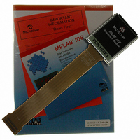
PCM18XK1
Description
MODULE PROC PIC18F8680,6680,8565
Manufacturer
Microchip Technology
Datasheet
1.PCM18XK1.pdf
(496 pages)
Specifications of PCM18XK1
Accessory Type
Processor Module
Lead Free Status / RoHS Status
Not applicable / Not applicable
For Use With/related Products
ICE2000
For Use With
ICE2000 - EMULATOR MPLAB-ICE 2000 POD
Lead Free Status / Rohs Status
Lead free / RoHS Compliant


2.4
The EC, ECIO, EC+PLL and EC+SPLL Oscillator
modes require an external clock source to be con-
nected to the OSC1 pin. The feedback device between
OSC1 and OSC2 is turned off in these modes to save
current. There is a maximum 1.5 s start-up required
after a Power-on Reset, or wake-up from Sleep mode.
In the EC Oscillator mode, the oscillator frequency
divided by 4 is available on the OSC2 pin. This signal
may be used for test purposes or to synchronize other
logic. Figure 2-4 shows the pin connections for the EC
Oscillator mode.
FIGURE 2-4:
The ECIO Oscillator mode functions like the EC mode,
except that the OSC2 pin becomes an additional gen-
eral purpose I/O pin. The I/O pin becomes bit 6 of
PORTA (RA6). Figure 2-5 shows the pin connections
for the ECIO Oscillator mode.
FIGURE 2-5:
FIGURE 2-6:
2004 Microchip Technology Inc.
Clock from
Ext. System
Clock from
Ext. System
External Clock Input
F
RA6
OSC
PLL Enable
/4
EXTERNAL CLOCK INPUT
OPERATION
(EC CONFIGURATION)
EXTERNAL CLOCK INPUT
OPERATION
(ECIO CONFIGURATION)
PLL BLOCK DIAGRAM
F
IN
OSC1
OSC2
OSC1
I/O (OSC2)
Comparator
F
OUT
PIC18FXX80/XX85
Phase
PIC18FXX80/XX85
PIC18F6585/8585/6680/8680
Loop
Filter
Divide by 4
2.5
A Phase Locked Loop circuit is provided as a
programmable option for users that want to multiply the
frequency of the incoming oscillator signal by 4. For an
input clock frequency of 10 MHz, the internal clock
frequency will be multiplied to 40 MHz. This is useful for
customers who are concerned with EMI due to
high-frequency crystals.
The PLL can only be enabled when the oscillator config-
uration bits are programmed for High-Speed Oscillator
or External Clock mode. If they are programmed for any
other mode, the PLL is not enabled and the system clock
will come directly from OSC1. There are two types of
PLL modes: Software Controlled PLL and Configuration
bits Controlled PLL. In Software Controlled PLL mode,
PIC18F6585/8585/6680/8680 executes at regular clock
frequency after all Reset conditions. During execution,
application can enable PLL and switch to 4x clock
frequency operation by setting the PLLEN bit in the
OSCCON register. In Configuration bits Controlled PLL
mode, PIC18F6585/8585/6680/8680 always executes
with 4x clock frequency.
The type of PLL is selected by programming the
FOSC<3:0> configuration bits in the CONFIG1H
Configuration register. The oscillator mode is specified
during device programming.
A PLL lock timer is used to ensure that the PLL has
locked before device execution starts. The PLL lock
timer has a time-out that is called T
VCO
Phase Locked Loop (PLL)
SYSCLK
PLL
DS30491C-page 25
.
Related parts for PCM18XK1
Image
Part Number
Description
Manufacturer
Datasheet
Request
R

Part Number:
Description:
Manufacturer:
Microchip Technology Inc.
Datasheet:
Part Number:
Description:
Manufacturer:
Microchip Technology Inc.
Datasheet:
Part Number:
Description:
Manufacturer:
Microchip Technology Inc.
Datasheet:
Part Number:
Description:
Manufacturer:
Microchip Technology Inc.
Datasheet:
Part Number:
Description:
Manufacturer:
Microchip Technology Inc.
Datasheet:
Part Number:
Description:
Manufacturer:
Microchip Technology Inc.
Datasheet:
Part Number:
Description:
Manufacturer:
Microchip Technology Inc.
Datasheet:
Part Number:
Description:
Manufacturer:
Microchip Technology Inc.
Datasheet: