PCM18XK1 Microchip Technology, PCM18XK1 Datasheet - Page 116
PCM18XK1
Manufacturer Part Number
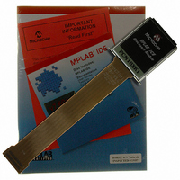
PCM18XK1
Description
MODULE PROC PIC18F8680,6680,8565
Manufacturer
Microchip Technology
Datasheet
1.PCM18XK1.pdf
(496 pages)
Specifications of PCM18XK1
Accessory Type
Processor Module
Lead Free Status / RoHS Status
Not applicable / Not applicable
For Use With/related Products
ICE2000
For Use With
ICE2000 - EMULATOR MPLAB-ICE 2000 POD
Lead Free Status / Rohs Status
Lead free / RoHS Compliant


PIC18F6585/8585/6680/8680
9.2
The PIR registers contain the individual flag bits for the
peripheral interrupts. Due to the number of peripheral
interrupt sources, there are three Peripheral Interrupt
Flag registers (PIR1, PIR2 and PIR3).
REGISTER 9-4:
DS30491C-page 114
PIR Registers
bit 7
bit 6
bit 5
bit 4
bit 3
bit 2
bit 1
bit 0
PIR1: PERIPHERAL INTERRUPT REQUEST (FLAG) REGISTER 1
bit 7
PSPIF: Parallel Slave Port Read/Write Interrupt Flag bit
1 = A read or a write operation has taken place (must be cleared in software)
0 = No read or write has occurred
ADIF: A/D Converter Interrupt Flag bit
1 = An A/D conversion completed (must be cleared in software)
0 = The A/D conversion is not complete
RCIF: USART Receive Interrupt Flag bit
1 = The USART receive buffer, RCREG, is full (cleared when RCREG is read)
0 = The USART receive buffer is empty
TXIF: USART Transmit Interrupt Flag bit
1 = The USART transmit buffer, TXREG, is empty (cleared when TXREG is written)
0 = The USART transmit buffer is full
SSPIF: Master Synchronous Serial Port Interrupt Flag bit
1 = The transmission/reception is complete (must be cleared in software)
0 = Waiting to transmit/receive
CCP1IF: Enhanced CCP1 Interrupt Flag bit
Capture mode:
1 = A TMR1 register capture occurred (must be cleared in software)
0 = No TMR1 register capture occurred
Compare mode:
1 = A TMR1 register compare match occurred (must be cleared in software)
0 = No TMR1 register compare match occurred
PWM mode:
Unused in this mode.
TMR2IF: TMR2 to PR2 Match Interrupt Flag bit
1 = TMR2 to PR2 match occurred (must be cleared in software)
0 = No TMR2 to PR2 match occurred
TMR1IF: TMR1 Overflow Interrupt Flag bit
1 = TMR1 register overflowed (must be cleared in software)
0 = TMR1 register did not overflow
Legend:
R = Readable bit
- n = Value at POR
PSPIF
R/W-0
Note 1: Available in Microcontroller mode only.
(1)
R/W-0
ADIF
RCIF
R-0
W = Writable bit
‘1’ = Bit is set
TXIF
R-0
Note 1: Interrupt flag bits are set when an interrupt
2: User software should ensure the appropri-
SSPIF
R/W-0
U = Unimplemented bit, read as ‘0’
‘0’ = Bit is cleared
condition occurs regardless of the state of
its corresponding enable bit or the global
enable bit, GIE (INTCON<7>).
ate interrupt flag bits are cleared prior to
enabling an interrupt, and after servicing
that interrupt.
(1)
CCP1IF
R/W-0
2004 Microchip Technology Inc.
TMR2IF
R/W-0
x = Bit is unknown
TMR1IF
R/W-0
bit 0
Related parts for PCM18XK1
Image
Part Number
Description
Manufacturer
Datasheet
Request
R

Part Number:
Description:
Manufacturer:
Microchip Technology Inc.
Datasheet:
Part Number:
Description:
Manufacturer:
Microchip Technology Inc.
Datasheet:
Part Number:
Description:
Manufacturer:
Microchip Technology Inc.
Datasheet:
Part Number:
Description:
Manufacturer:
Microchip Technology Inc.
Datasheet:
Part Number:
Description:
Manufacturer:
Microchip Technology Inc.
Datasheet:
Part Number:
Description:
Manufacturer:
Microchip Technology Inc.
Datasheet:
Part Number:
Description:
Manufacturer:
Microchip Technology Inc.
Datasheet:
Part Number:
Description:
Manufacturer:
Microchip Technology Inc.
Datasheet: