PCM18XK1 Microchip Technology, PCM18XK1 Datasheet - Page 357
PCM18XK1
Manufacturer Part Number
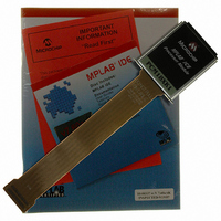
PCM18XK1
Description
MODULE PROC PIC18F8680,6680,8565
Manufacturer
Microchip Technology
Datasheet
1.PCM18XK1.pdf
(496 pages)
Specifications of PCM18XK1
Accessory Type
Processor Module
Lead Free Status / RoHS Status
Not applicable / Not applicable
For Use With/related Products
ICE2000
For Use With
ICE2000 - EMULATOR MPLAB-ICE 2000 POD
Lead Free Status / Rohs Status
Lead free / RoHS Compliant


24.2
The Watchdog Timer is a free-running, on-chip RC
oscillator which does not require any external compo-
nents. This RC oscillator is separate from the RC
oscillator of the OSC1/CLKI pin. That means that the
WDT will run even if the clock on the OSC1/CLKI and
OSC2/CLKO/RA6 pins of the device has been stopped,
for example, by execution of a SLEEP instruction.
During normal operation, a WDT time-out generates a
device Reset (Watchdog Timer Reset). If the device is
in Sleep mode, a WDT time-out causes the device to
wake-up and continue with normal operation (Watch-
dog Timer wake-up). The TO bit in the RCON register
will be cleared upon a WDT time-out.
The Watchdog Timer is enabled/disabled by a device
configuration bit. If the WDT is enabled, software
execution may not disable this function. When the
WDTEN configuration bit is cleared, the SWDTEN bit
enables/disables the operation of the WDT.
REGISTER 24-15: WDTCON REGISTER
2004 Microchip Technology Inc.
Watchdog Timer (WDT)
bit 7-1
bit 0
bit 7
Unimplemented: Read as ‘0’
SWDTEN: Software Controlled Watchdog Timer Enable bit
1 = Watchdog Timer is on
0 = Watchdog Timer is turned off if the WDTEN configuration bit in the Configuration register = 0
Legend:
R = Readable bit
- n = Value at POR
U-0
—
U-0
—
PIC18F6585/8585/6680/8680
U-0
—
W = Writable bit
‘1’ = Bit is set
U-0
The WDT time-out period values may be found in
Section 27.0 “Electrical Characteristics” under
parameter #31. Values for the WDT postscaler may be
assigned using the configuration bits.
24.2.1
Register 24-15 shows the WDTCON register. This is a
readable and writable register which contains a control
bit that allows software to override the WDT enable
configuration bit, only when the configuration bit has
disabled the WDT.
—
Note 1: The CLRWDT and SLEEP instructions
2: When a CLRWDT instruction is executed
CONTROL REGISTER
U-0
U = Unimplemented bit, read as ‘0’
‘0’ = Bit is cleared
clear the WDT and the postscaler if
assigned to the WDT and prevent it from
timing out and generating a device Reset
condition.
and the postscaler is assigned to the
WDT, the postscaler count will be cleared
but the postscaler assignment is not
changed.
—
U-0
—
x = Bit is unknown
U-0
—
DS30491C-page 355
SWDTEN
R/W-0
bit 0
Related parts for PCM18XK1
Image
Part Number
Description
Manufacturer
Datasheet
Request
R

Part Number:
Description:
Manufacturer:
Microchip Technology Inc.
Datasheet:
Part Number:
Description:
Manufacturer:
Microchip Technology Inc.
Datasheet:
Part Number:
Description:
Manufacturer:
Microchip Technology Inc.
Datasheet:
Part Number:
Description:
Manufacturer:
Microchip Technology Inc.
Datasheet:
Part Number:
Description:
Manufacturer:
Microchip Technology Inc.
Datasheet:
Part Number:
Description:
Manufacturer:
Microchip Technology Inc.
Datasheet:
Part Number:
Description:
Manufacturer:
Microchip Technology Inc.
Datasheet:
Part Number:
Description:
Manufacturer:
Microchip Technology Inc.
Datasheet: