PCM18XK1 Microchip Technology, PCM18XK1 Datasheet - Page 173
PCM18XK1
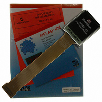
Manufacturer Part Number
PCM18XK1
Description
MODULE PROC PIC18F8680,6680,8565
Manufacturer
Microchip Technology
Datasheet
1.PCM18XK1.pdf
(496 pages)
Specifications of PCM18XK1
Accessory Type
Processor Module
Lead Free Status / RoHS Status
Not applicable / Not applicable
For Use With/related Products
ICE2000
For Use With
ICE2000 - EMULATOR MPLAB-ICE 2000 POD
Lead Free Status / Rohs Status
Lead free / RoHS Compliant


15.3
In Compare mode, the 16-bit CCPRx register value is
constantly compared against either the TMR1 register
pair value or the TMR3 register pair value. When a
match occurs, the CCPx pin can have one of the
following actions:
• Driven high
• Driven low
• Toggle output (high-to-low or low-to-high)
• Remains unchanged
The action on the pin is based on the value of control
bits, CCPxM3:CCPxM0. At the same time, interrupt
flag bit, CCPxIF, is set.
When configured to drive the CCP pin, the CCP1 pin
cannot be changed; CCP1 module controls the pin.
15.3.1
The user must configure the CCPx pin as an output by
clearing the appropriate TRIS bit.
By default, the CCP2 pin is multiplexed with RC1.
Alternately, it can also be multiplexed with either RB3
or RE7. This is done by changing the CCP2MX
configuration bit.
FIGURE 15-2:
2004 Microchip Technology Inc.
Note:
RC2/CCP1 pin
RC1/CCP2 pin
Special Event Trigger will:
Compare Mode
Reset Timer1 or Timer3, but not set Timer1 or Timer3 interrupt flag bit
and set bit GO/DONE (ADCON0<2>)
which starts an A/D conversion (CCP2 only)
CCP PIN CONFIGURATION
Clearing the CCPxCON register will force
the CCPx compare output latch to the
default low level. This is not the data latch.
Output Enable
Output Enable
TRISC<2>
TRISC<1>
COMPARE MODE OPERATION BLOCK DIAGRAM
Q
Q
R
R
S
S
Special Event Trigger
CCP1CON<3:0>
CCP2CON<3:0>
Mode Select
Mode Select
Output
Output
Logic
Logic
PIC18F6585/8585/6680/8680
Set Flag bit CCP1IF
Set Flag bit CCP2IF
Match
Match
15.3.2
The timer used with each CCP module is selected in
the T3CCP2:T3CCP1 bits of the T3CON register.
Timer1 and/or Timer3 must be running in Timer mode,
or Synchronized Counter mode, if the CCP module is
using the compare feature. In Asynchronous Counter
mode, the compare operation may not work.
15.3.3
When generate software interrupt is chosen, the CCPx
pin is not affected. Only a CCP interrupt is generated (if
enabled).
15.3.4
In this mode, an internal hardware trigger is generated
which may be used to initiate an action.
The special event trigger output of CCP1 resets either
the TMR1 or TMR3 register pair. This allows the CCPR1
register to effectively be a 16-bit programmable period
register for TMR1 or TMR3.
Additionally, the CCP2 special event trigger will start an
A/D conversion if the A/D module is enabled.
Note:
T3CCP1
T3CCP2
TMR1H
TIMER1/TIMER3 MODE SELECTION
SOFTWARE INTERRUPT MODE
SPECIAL EVENT TRIGGER
The special event trigger from the CCPx
module will not set the Timer1 or Timer3
interrupt flag bits.
T3CCP2
TMR1L
CCPR1H CCPR1L
CCPR2H CCPR2L
Comparator
Comparator
0
0
1
1
TMR3H
DS30491C-page 171
TMR3L
Related parts for PCM18XK1
Image
Part Number
Description
Manufacturer
Datasheet
Request
R

Part Number:
Description:
Manufacturer:
Microchip Technology Inc.
Datasheet:
Part Number:
Description:
Manufacturer:
Microchip Technology Inc.
Datasheet:
Part Number:
Description:
Manufacturer:
Microchip Technology Inc.
Datasheet:
Part Number:
Description:
Manufacturer:
Microchip Technology Inc.
Datasheet:
Part Number:
Description:
Manufacturer:
Microchip Technology Inc.
Datasheet:
Part Number:
Description:
Manufacturer:
Microchip Technology Inc.
Datasheet:
Part Number:
Description:
Manufacturer:
Microchip Technology Inc.
Datasheet:
Part Number:
Description:
Manufacturer:
Microchip Technology Inc.
Datasheet: