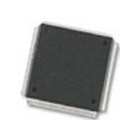
MC68376BAMFT20 Freescale Semiconductor, MC68376BAMFT20 Datasheet - Page 382

MC68376BAMFT20
Manufacturer Part Number
MC68376BAMFT20
Description
Manufacturer
Freescale Semiconductor
Datasheet
1.MC68376BAMFT20.pdf
(434 pages)
Specifications of MC68376BAMFT20
Cpu Family
68K/M683xx
Device Core
ColdFire
Device Core Size
32b
Frequency (max)
20MHz
Interface Type
QSPI/SCI
Program Memory Type
ROM
Program Memory Size
8KB
Total Internal Ram Size
7.5KB
# I/os (max)
18
Number Of Timers - General Purpose
2
Operating Supply Voltage (typ)
5V
Operating Supply Voltage (max)
5.25V
Operating Supply Voltage (min)
4.75V
On-chip Adc
16-chx10-bit
Instruction Set Architecture
RISC
Operating Temp Range
-40C to 125C
Operating Temperature Classification
Automotive
Mounting
Surface Mount
Pin Count
160
Package Type
PQFP
Lead Free Status / Rohs Status
Not Compliant
Available stocks
Company
Part Number
Manufacturer
Quantity
Price
Company:
Part Number:
MC68376BAMFT20
Manufacturer:
FREESCAL
Quantity:
245
- Current page: 382 of 434
- Download datasheet (7Mb)
IL[2:0] — Interrupt Level
IARB3 — Interrupt Arbitration Bit 3
WOR — Wired-OR Mode
BSL — Bus Select
IN — Input Pin Status
D-64
MOTOROLA
The FLAG bit is set by hardware and cleared by software, or by system reset. Clear
the FLAG bit either by writing a zero to it, having first read the bit as a one, or by se-
lecting the DIS mode.
When the DASM generates an interrupt request, IL[2:0] determines which of the
interrupt request signals is asserted. When a request is acknowledged, the CTM4
compares IL[2:0] to a mask value supplied by the CPU32 to determine whether to
respond. IL[2:0] must have a value in the range of $0 (interrupts disabled) to $7
(highest priority).
This bit and the IARB[2:0] field in BIUMCR are concatenated to determine the interrupt
arbitration number for the submodule requesting interrupt service. Refer to D.7.1 BIU
Module Configuration Register for more information on IARB[2:0].
In the DIS, IPWM, IPM and IC modes, the WOR bit is not used. Reading this bit returns
the value that was previously written.
In the OCB, OCAB and OPWM modes, the WOR bit selects whether the output buffer
is configured for open-drain or normal operation.
This bit selects the time base bus connected to the DASM.
In the DIS, IPWM, IPM and IC modes, this read-only status bit reflects the logic level
on the input pin.
In the OCB, OCAB and OPWM modes, reading this bit returns the value latched on
the output flip-flop, after EDPOL polarity selection.
Writing to this bit has no effect.
0 = Output buffer operates in normal mode.
1 = Output buffer operates in open-drain mode.
0 = DASM is connected to time base bus A.
1 = DASM is connected to time base bus B.
OPWM
OCAB
Mode
IPWM
OCB
IPM
DIS
IC
FLAG bit is reset
FLAG bit is set each time there is a capture on channel A
FLAG bit is set each time there is a capture on channel A, except for the first time
FLAG bit is set each time there is a capture on channel A
FLAG bit is set each time there is a successful comparison on channel B
FLAG bit is set each time there is a successful comparison on either channel A or B
FLAG bit is set each time there is a successful comparison on channel A
Table D-44 DASM Mode Flag Status Bit States
REGISTER SUMMARY
Flag Status Bit State
USER’S MANUAL
MC68336/376
Related parts for MC68376BAMFT20
Image
Part Number
Description
Manufacturer
Datasheet
Request
R
Part Number:
Description:
Manufacturer:
Freescale Semiconductor, Inc
Datasheet:
Part Number:
Description:
Manufacturer:
Freescale Semiconductor, Inc
Datasheet:
Part Number:
Description:
Manufacturer:
Freescale Semiconductor, Inc
Datasheet:
Part Number:
Description:
Manufacturer:
Freescale Semiconductor, Inc
Datasheet:
Part Number:
Description:
Manufacturer:
Freescale Semiconductor, Inc
Datasheet:
Part Number:
Description:
Manufacturer:
Freescale Semiconductor, Inc
Datasheet:
Part Number:
Description:
Manufacturer:
Freescale Semiconductor, Inc
Datasheet:
Part Number:
Description:
Manufacturer:
Freescale Semiconductor, Inc
Datasheet:
Part Number:
Description:
Manufacturer:
Freescale Semiconductor, Inc
Datasheet:
Part Number:
Description:
Manufacturer:
Freescale Semiconductor, Inc
Datasheet:
Part Number:
Description:
Manufacturer:
Freescale Semiconductor, Inc
Datasheet:
Part Number:
Description:
Manufacturer:
Freescale Semiconductor, Inc
Datasheet:
Part Number:
Description:
Manufacturer:
Freescale Semiconductor, Inc
Datasheet:
Part Number:
Description:
Manufacturer:
Freescale Semiconductor, Inc
Datasheet:
Part Number:
Description:
Manufacturer:
Freescale Semiconductor, Inc
Datasheet:


