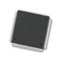
MC68376BAMFT20 Freescale Semiconductor, MC68376BAMFT20 Datasheet - Page 128

MC68376BAMFT20
Manufacturer Part Number
MC68376BAMFT20
Description
Manufacturer
Freescale Semiconductor
Datasheet
1.MC68376BAMFT20.pdf
(434 pages)
Specifications of MC68376BAMFT20
Cpu Family
68K/M683xx
Device Core
ColdFire
Device Core Size
32b
Frequency (max)
20MHz
Interface Type
QSPI/SCI
Program Memory Type
ROM
Program Memory Size
8KB
Total Internal Ram Size
7.5KB
# I/os (max)
18
Number Of Timers - General Purpose
2
Operating Supply Voltage (typ)
5V
Operating Supply Voltage (max)
5.25V
Operating Supply Voltage (min)
4.75V
On-chip Adc
16-chx10-bit
Instruction Set Architecture
RISC
Operating Temp Range
-40C to 125C
Operating Temperature Classification
Automotive
Mounting
Surface Mount
Pin Count
160
Package Type
PQFP
Lead Free Status / Rohs Status
Not Compliant
Available stocks
Company
Part Number
Manufacturer
Quantity
Price
Company:
Part Number:
MC68376BAMFT20
Manufacturer:
FREESCAL
Quantity:
245
- Current page: 128 of 434
- Download datasheet (7Mb)
5.7.9 Reset Processing Summary
5.7.10 Reset Status Register
5.8 Interrupts
5.8.1 Interrupt Exception Processing
5-50
MOTOROLA
To prevent write cycles in progress from being corrupted, a reset is recognized at the
end of a bus cycle instead of at an instruction boundary. Any processing in progress
at the time a reset occurs is aborted. After SIM reset control logic has synchronized an
internal or external reset request, the MSTRST signal is asserted.
The following events take place when MSTRST is asserted:
The following events take place when MSTRST is negated after assertion.
The reset status register (RSR) contains a bit for each reset source in the MCU. When
a reset occurs, a bit corresponding to the reset type is set. When multiple causes of
reset occur at the same time, only one bit in RSR may be set. The reset status register
is updated by the reset control logic when the RESET signal is released. Refer to D.2.4
Reset Status Register for more information.
Interrupt recognition and servicing involve complex interaction between the SIM, the
CPU32, and a device or module requesting interrupt service.
The following paragraphs provide an overview of the entire interrupt process. Chip-
select logic can also be used to terminate the IACK cycle with either AVEC or DSACK.
Refer to 5.9 Chip-Selects for more information.
The CPU32 processes interrupts as a type of asynchronous exception. An exception
is an event that preempts normal processing. Each exception has an assigned vector
in an exception vector table that points to an associated handler routine. The CPU32
uses vector numbers to calculate displacement into the table. During exception pro-
cessing, the CPU fetches the appropriate vector and executes the exception handler
routine to which the vector points.
A. Instruction execution is aborted.
B. The status register is initialized.
C. The vector base register is initialized to $000000.
A. The CPU32 samples the BKPT input.
B. The CPU32 fetches the reset vector:
C. The CPU32 fetches and begins decoding the first instruction to be executed.
1. The T0 and T1 bits are cleared to disable tracing.
2. The S bit is set to establish supervisor privilege level.
3. The interrupt priority mask is set to $7, disabling all interrupts below
1. The first long word of the vector is loaded into the interrupt stack pointer.
2. The second long word of the vector is loaded into the program counter.
3. Vectors can be fetched from external ROM enabled by the CSBOOT signal.
priority 7.
SYSTEM INTEGRATION MODULE
USER’S MANUAL
MC68336/376
Related parts for MC68376BAMFT20
Image
Part Number
Description
Manufacturer
Datasheet
Request
R
Part Number:
Description:
Manufacturer:
Freescale Semiconductor, Inc
Datasheet:
Part Number:
Description:
Manufacturer:
Freescale Semiconductor, Inc
Datasheet:
Part Number:
Description:
Manufacturer:
Freescale Semiconductor, Inc
Datasheet:
Part Number:
Description:
Manufacturer:
Freescale Semiconductor, Inc
Datasheet:
Part Number:
Description:
Manufacturer:
Freescale Semiconductor, Inc
Datasheet:
Part Number:
Description:
Manufacturer:
Freescale Semiconductor, Inc
Datasheet:
Part Number:
Description:
Manufacturer:
Freescale Semiconductor, Inc
Datasheet:
Part Number:
Description:
Manufacturer:
Freescale Semiconductor, Inc
Datasheet:
Part Number:
Description:
Manufacturer:
Freescale Semiconductor, Inc
Datasheet:
Part Number:
Description:
Manufacturer:
Freescale Semiconductor, Inc
Datasheet:
Part Number:
Description:
Manufacturer:
Freescale Semiconductor, Inc
Datasheet:
Part Number:
Description:
Manufacturer:
Freescale Semiconductor, Inc
Datasheet:
Part Number:
Description:
Manufacturer:
Freescale Semiconductor, Inc
Datasheet:
Part Number:
Description:
Manufacturer:
Freescale Semiconductor, Inc
Datasheet:
Part Number:
Description:
Manufacturer:
Freescale Semiconductor, Inc
Datasheet:


