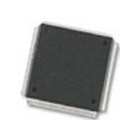
MC68376BAMFT20 Freescale Semiconductor, MC68376BAMFT20 Datasheet - Page 129

MC68376BAMFT20
Manufacturer Part Number
MC68376BAMFT20
Description
Manufacturer
Freescale Semiconductor
Datasheet
1.MC68376BAMFT20.pdf
(434 pages)
Specifications of MC68376BAMFT20
Cpu Family
68K/M683xx
Device Core
ColdFire
Device Core Size
32b
Frequency (max)
20MHz
Interface Type
QSPI/SCI
Program Memory Type
ROM
Program Memory Size
8KB
Total Internal Ram Size
7.5KB
# I/os (max)
18
Number Of Timers - General Purpose
2
Operating Supply Voltage (typ)
5V
Operating Supply Voltage (max)
5.25V
Operating Supply Voltage (min)
4.75V
On-chip Adc
16-chx10-bit
Instruction Set Architecture
RISC
Operating Temp Range
-40C to 125C
Operating Temperature Classification
Automotive
Mounting
Surface Mount
Pin Count
160
Package Type
PQFP
Lead Free Status / Rohs Status
Not Compliant
Available stocks
Company
Part Number
Manufacturer
Quantity
Price
Company:
Part Number:
MC68376BAMFT20
Manufacturer:
FREESCAL
Quantity:
245
- Current page: 129 of 434
- Download datasheet (7Mb)
5.8.2 Interrupt Priority and Recognition
MC68336/376
USER’S MANUAL
At the release of reset, the exception vector table is located beginning at address
$000000. This value can be changed by programming the vector base register (VBR)
with a new value. Multiple vector tables can be used. Refer to 4.9 Exception Process-
ing for more information.
The CPU32 provides seven levels of interrupt priority (1-7), seven automatic interrupt
vectors, and 200 assignable interrupt vectors. All interrupts with priorities less than
seven can be masked by the interrupt priority (IP) field in status register.
There are seven interrupt request signals (IRQ[7:1]). These signals are used internally
on the IMB, and have corresponding pins for external interrupt service requests. The
CPU32 treats all interrupt requests as though they come from internal modules; exter-
nal interrupt requests are treated as interrupt service requests from the SIM. Each of
the interrupt request signals corresponds to an interrupt priority. IRQ1 has the lowest
priority and IRQ7 the highest.
Interrupt recognition is determined by interrupt priority level and interrupt priority (IP)
mask value. The interrupt priority mask consists of three bits in the CPU32 status reg-
ister. Binary values %000 to %111 provide eight priority masks. Masks prevent an in-
terrupt request of a priority less than or equal to the mask value from being recognized
and processed. IRQ7, however, is always recognized, even if the mask value is %111.
IRQ[7:1] are active-low level-sensitive inputs. The low on the pin must remain asserted
until an interrupt acknowledge cycle corresponding to that level is detected.
IRQ7 is transition-sensitive as well as level-sensitive: a level-7 interrupt is not detected
unless a falling edge transition is detected on the IRQ7 line. This prevents redundant
servicing and stack overflow. A non-maskable interrupt is generated each time IRQ7
is asserted as well as each time the priority mask is written while IRQ7 is asserted. If
IRQ7 is asserted and the IP mask is written to any new value (including %111), IRQ7
will be recognized as a new IRQ7.
Interrupt requests are sampled on consecutive falling edges of the system clock. In-
terrupt request input circuitry has hysteresis. To be valid, a request signal must be as-
serted for at least two consecutive clock periods. Valid requests do not cause
immediate exception processing, but are left pending. Pending requests are pro-
cessed at instruction boundaries or when exception processing of higher-priority
interrupts is complete.
Exceptions such as “address error” are not interrupts and have no
“level” associated. Exceptions cannot ever be masked.
SYSTEM INTEGRATION MODULE
NOTE
MOTOROLA
5-51
Related parts for MC68376BAMFT20
Image
Part Number
Description
Manufacturer
Datasheet
Request
R
Part Number:
Description:
Manufacturer:
Freescale Semiconductor, Inc
Datasheet:
Part Number:
Description:
Manufacturer:
Freescale Semiconductor, Inc
Datasheet:
Part Number:
Description:
Manufacturer:
Freescale Semiconductor, Inc
Datasheet:
Part Number:
Description:
Manufacturer:
Freescale Semiconductor, Inc
Datasheet:
Part Number:
Description:
Manufacturer:
Freescale Semiconductor, Inc
Datasheet:
Part Number:
Description:
Manufacturer:
Freescale Semiconductor, Inc
Datasheet:
Part Number:
Description:
Manufacturer:
Freescale Semiconductor, Inc
Datasheet:
Part Number:
Description:
Manufacturer:
Freescale Semiconductor, Inc
Datasheet:
Part Number:
Description:
Manufacturer:
Freescale Semiconductor, Inc
Datasheet:
Part Number:
Description:
Manufacturer:
Freescale Semiconductor, Inc
Datasheet:
Part Number:
Description:
Manufacturer:
Freescale Semiconductor, Inc
Datasheet:
Part Number:
Description:
Manufacturer:
Freescale Semiconductor, Inc
Datasheet:
Part Number:
Description:
Manufacturer:
Freescale Semiconductor, Inc
Datasheet:
Part Number:
Description:
Manufacturer:
Freescale Semiconductor, Inc
Datasheet:
Part Number:
Description:
Manufacturer:
Freescale Semiconductor, Inc
Datasheet:


