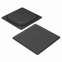
DS33R41+ Maxim Integrated Products, DS33R41+ Datasheet - Page 90

DS33R41+
Manufacturer Part Number
DS33R41+
Description
IC TXRX ETHERNET MAP 400-BGA
Manufacturer
Maxim Integrated Products
Type
Transceiverr
Datasheet
1.DS33R41.pdf
(335 pages)
Specifications of DS33R41+
Number Of Drivers/receivers
4/4
Protocol
T1/E1/J1
Voltage - Supply
3.14 V ~ 3.47 V
Mounting Type
Surface Mount
Package / Case
400-BGA
Lead Free Status / RoHS Status
Lead free / RoHS Compliant
- Current page: 90 of 335
- Download datasheet (2Mb)
DS33R41 Inverse-Multiplexing Ethernet Mapper with Quad Integrated T1/E1/J1 Transceivers
10.16 Additional (Sa) and International (Si) Bit Operation (E1 Only)
When operated in the E1 mode, the transceiver provides two methods for accessing the Sa and the Si bits. The
first method involves using the internal TR.RAF/TR.RNAF and TR.TAF/TR.TNAF registers (Section 10.16.1). The
second method, which is covered in Section 10.16.2, involves an expanded version of the first method.
10.16.1 Method 1: Internal Register Scheme Based on Double-Frame
On the receive side, the TR.RAF and TR.RNAF registers always report the data as it received in the Sa and Si bit
locations. The TR.RAF and TR.RNAF registers are updated on align-frame boundaries. The setting of the receive
align frame bit in Status Register 4 (TR.SR4.0) indicates that the contents of the TR.RAF and TR.RNAF have been
updated. The host can use the TR.SR4.0 bit to know when to read the TR.RAF and TR.RNAF registers. The host
has 250μs to retrieve the data before it is lost.
On the transmit side, data is sampled from the TR.TAF and TR.TNAF registers with the setting of the transmit align
frame bit in Status Register 4 (TR.SR4.3). The host can use the TR.SR4.3 bit to know when to update the TR.TAF
and TR.TNAF registers. It has 250μs to update the data or else the old data is retransmitted. If the TR.TAF and
TR.TNAF registers are only being used to source the align frame and nonalign frame-sync patterns, then
the host need only write once to these registers. Data in the Si bit position is overwritten if either the framer is
(1) programmed to source the Si bits from the TSERI pin, (2) in the CRC4 mode, or (3) has automatic E-bit
insertion enabled. Data in the Sa bit position is overwritten if any of the TR.E1TCR2.3 to TR.E1TCR2.7 bits are set
to 1.
10.16.2 Method 2: Internal Register Scheme Based on CRC4 Multiframe
The receive side contains a set of eight registers (TR.RSiAF, TR.RSiNAF, TR.RRA, and TR.RSa4–TR.RSa8) that
report the Si and Sa bits as they are received. These registers are updated with the setting of the receive CRC4
multiframe bit in Status Register 2 (TR.SR4.1). The host can use the TR.SR4.1 bit to know when to read these
registers. The user has 2ms to retrieve the data before it is lost. The MSB of each register is the first received. See
the following register descriptions for more details.
The transmit side also contains a set of eight registers (TR.TSiAF, TR.TSiNAF, TR.TRA, and TR.TSa4–TR.TSa8)
that, through the transmit Sa bit control register (TR.TSACR), can be programmed to insert Si and Sa data. Data is
sampled from these registers with the setting of the transmit multiframe bit in Status Register 2 (TR.SR4.4). The
host can use the TR.SR4.4 bit to know when to update these registers. It has 2ms to update the data or else the
old data is retransmitted. The MSB of each register is the first bit transmitted. See the register descriptions for
more details.
90 of 335
Related parts for DS33R41+
Image
Part Number
Description
Manufacturer
Datasheet
Request
R

Part Number:
Description:
MAX7528KCWPMaxim Integrated Products [CMOS Dual 8-Bit Buffered Multiplying DACs]
Manufacturer:
Maxim Integrated Products
Datasheet:

Part Number:
Description:
Single +5V, fully integrated, 1.25Gbps laser diode driver.
Manufacturer:
Maxim Integrated Products
Datasheet:

Part Number:
Description:
Single +5V, fully integrated, 155Mbps laser diode driver.
Manufacturer:
Maxim Integrated Products
Datasheet:

Part Number:
Description:
VRD11/VRD10, K8 Rev F 2/3/4-Phase PWM Controllers with Integrated Dual MOSFET Drivers
Manufacturer:
Maxim Integrated Products
Datasheet:

Part Number:
Description:
Highly Integrated Level 2 SMBus Battery Chargers
Manufacturer:
Maxim Integrated Products
Datasheet:

Part Number:
Description:
Current Monitor and Accumulator with Integrated Sense Resistor; ; Temperature Range: -40°C to +85°C
Manufacturer:
Maxim Integrated Products

Part Number:
Description:
TSSOP 14/A°/RS-485 Transceivers with Integrated 100O/120O Termination Resis
Manufacturer:
Maxim Integrated Products

Part Number:
Description:
TSSOP 14/A°/RS-485 Transceivers with Integrated 100O/120O Termination Resis
Manufacturer:
Maxim Integrated Products

Part Number:
Description:
QFN 16/A°/AC-DC and DC-DC Peak-Current-Mode Converters with Integrated Step
Manufacturer:
Maxim Integrated Products

Part Number:
Description:
TDFN/A/65V, 1A, 600KHZ, SYNCHRONOUS STEP-DOWN REGULATOR WITH INTEGRATED SWI
Manufacturer:
Maxim Integrated Products

Part Number:
Description:
Integrated Temperature Controller f
Manufacturer:
Maxim Integrated Products

Part Number:
Description:
SOT23-6/I°/45MHz to 650MHz, Integrated IF VCOs with Differential Output
Manufacturer:
Maxim Integrated Products

Part Number:
Description:
SOT23-6/I°/45MHz to 650MHz, Integrated IF VCOs with Differential Output
Manufacturer:
Maxim Integrated Products

Part Number:
Description:
EVALUATION KIT/2.4GHZ TO 2.5GHZ 802.11G/B RF TRANSCEIVER WITH INTEGRATED PA
Manufacturer:
Maxim Integrated Products

Part Number:
Description:
QFN/E/DUAL PCIE/SATA HIGH SPEED SWITCH WITH INTEGRATED BIAS RESISTOR
Manufacturer:
Maxim Integrated Products
Datasheet:


