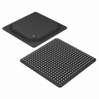
DS33R41+ Maxim Integrated Products, DS33R41+ Datasheet - Page 200

DS33R41+
Manufacturer Part Number
DS33R41+
Description
IC TXRX ETHERNET MAP 400-BGA
Manufacturer
Maxim Integrated Products
Type
Transceiverr
Datasheet
1.DS33R41.pdf
(335 pages)
Specifications of DS33R41+
Number Of Drivers/receivers
4/4
Protocol
T1/E1/J1
Voltage - Supply
3.14 V ~ 3.47 V
Mounting Type
Surface Mount
Package / Case
400-BGA
Lead Free Status / RoHS Status
Lead free / RoHS Compliant
- Current page: 200 of 335
- Download datasheet (2Mb)
Register Name:
Register Description:
Register Address:
Bit #
Name
Default
Bit 7: MCLK Source Select (MCLKS). Selects the source of MCLK.
Bit 6: CRC-4 Recalculate (E1 Mode Only) (CRC4R).
BIT 5: Signaling Integration Enable (SIE).
Bit 4: Transmit RAI-CI Enable (TRAI-CI). Setting this bit causes the ESF RAI-CI code to be transmitted in the
FDL bit position.
Bit 3: Transmit AIS-CI Enable (TAIS-CI). Setting this bit and the TBL bit (TR.T1TCR1.1) causes the AIS-CI code
to be transmitted at TPOSO and TNEGO, as defined in ANSI T1.403.
Bit 2: Transmit Frame Mode Select (TFM)
Bit 1: Pulse Density Enforcer Enable (PDE). The framer always examines the transmit and receive data streams
for violations of these, which are required by ANSI T1.403: No more than 15 consecutive 0s and at least N 1s in
each and every time window of 8 x (N + 1) bits, where N = 1 through 23. Violations for the transmit and receive
data streams are reported in the TR.INFO1.6 and TR.INFO1.7 bits, respectively. When this bit is set to 1, the
T1/E1/J1 transceiver forces the transmitted stream to meet this requirement no matter the content of the
transmitted stream. When running B8ZS, this bit should be set to 0 since B8ZS encoded data streams cannot
violate the pulse density requirements.
Bit 0: Transmit Loop-Code Enable (TLOOP). See Section
0 = MCLK is sourced from the MCLK pin.
1 = MCLK is sourced from the TSYSCLK pin.
0 = Transmit CRC-4 Generation and Insertion operates in normal mode.
1 = Transmit CRC-4 operation according to G.706 Intermediate Path Recalculation Method.
0 = Signaling changes of state are reported upon any change in selected channels.
1 = Signaling must be stable for three multiframes before a change of state is reported.
0 = do not transmit the ESF RAI-CI code
1 = transmit the ESF RAI-CI code
0 = do not transmit the AIS-CI code
1 = transmit the AIS-CI code (TR.T1TCR1.1 must also be set = 1)
0 = D4 framing mode
1 = ESF framing mode
0 = disable transmit pulse density enforcer
1 = enable transmit pulse density enforcer
0 = transmit data normally
1 = replace normal transmitted data with repeating code as defined in registers TR.TCD1 and TR.TCD2
MCLKS
7
0
TR.T1CCR1
T1 Common Control Register 1
07h
CRC4R
6
0
SIE
5
0
TRAI-CI
200 of 335
4
0
10.20
TAIS-CI
for details.
3
0
TFM
2
0
PDE
1
0
TLOOP
0
0
Related parts for DS33R41+
Image
Part Number
Description
Manufacturer
Datasheet
Request
R

Part Number:
Description:
MAX7528KCWPMaxim Integrated Products [CMOS Dual 8-Bit Buffered Multiplying DACs]
Manufacturer:
Maxim Integrated Products
Datasheet:

Part Number:
Description:
Single +5V, fully integrated, 1.25Gbps laser diode driver.
Manufacturer:
Maxim Integrated Products
Datasheet:

Part Number:
Description:
Single +5V, fully integrated, 155Mbps laser diode driver.
Manufacturer:
Maxim Integrated Products
Datasheet:

Part Number:
Description:
VRD11/VRD10, K8 Rev F 2/3/4-Phase PWM Controllers with Integrated Dual MOSFET Drivers
Manufacturer:
Maxim Integrated Products
Datasheet:

Part Number:
Description:
Highly Integrated Level 2 SMBus Battery Chargers
Manufacturer:
Maxim Integrated Products
Datasheet:

Part Number:
Description:
Current Monitor and Accumulator with Integrated Sense Resistor; ; Temperature Range: -40°C to +85°C
Manufacturer:
Maxim Integrated Products

Part Number:
Description:
TSSOP 14/A°/RS-485 Transceivers with Integrated 100O/120O Termination Resis
Manufacturer:
Maxim Integrated Products

Part Number:
Description:
TSSOP 14/A°/RS-485 Transceivers with Integrated 100O/120O Termination Resis
Manufacturer:
Maxim Integrated Products

Part Number:
Description:
QFN 16/A°/AC-DC and DC-DC Peak-Current-Mode Converters with Integrated Step
Manufacturer:
Maxim Integrated Products

Part Number:
Description:
TDFN/A/65V, 1A, 600KHZ, SYNCHRONOUS STEP-DOWN REGULATOR WITH INTEGRATED SWI
Manufacturer:
Maxim Integrated Products

Part Number:
Description:
Integrated Temperature Controller f
Manufacturer:
Maxim Integrated Products

Part Number:
Description:
SOT23-6/I°/45MHz to 650MHz, Integrated IF VCOs with Differential Output
Manufacturer:
Maxim Integrated Products

Part Number:
Description:
SOT23-6/I°/45MHz to 650MHz, Integrated IF VCOs with Differential Output
Manufacturer:
Maxim Integrated Products

Part Number:
Description:
EVALUATION KIT/2.4GHZ TO 2.5GHZ 802.11G/B RF TRANSCEIVER WITH INTEGRATED PA
Manufacturer:
Maxim Integrated Products

Part Number:
Description:
QFN/E/DUAL PCIE/SATA HIGH SPEED SWITCH WITH INTEGRATED BIAS RESISTOR
Manufacturer:
Maxim Integrated Products
Datasheet:


