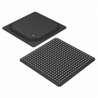
DS33R41+ Maxim Integrated Products, DS33R41+ Datasheet - Page 136

DS33R41+
Manufacturer Part Number
DS33R41+
Description
IC TXRX ETHERNET MAP 400-BGA
Manufacturer
Maxim Integrated Products
Type
Transceiverr
Datasheet
1.DS33R41.pdf
(335 pages)
Specifications of DS33R41+
Number Of Drivers/receivers
4/4
Protocol
T1/E1/J1
Voltage - Supply
3.14 V ~ 3.47 V
Mounting Type
Surface Mount
Package / Case
400-BGA
Lead Free Status / RoHS Status
Lead free / RoHS Compliant
- Current page: 136 of 335
- Download datasheet (2Mb)
Register Name:
Register Description:
Register Address:
Bit #
Name
Default
Bit 6: T1E1 Mode (T1E1). This bit determines if the IMUX operation is for T1 or E1 Mode.
Bit 5: Receive Enable (RXE). If this bit is set to 1, data will be received from the Serial Interface and passed to the
packet processor. If equal to 0, no data will be sent to the packet processor.
Bit 4: SEND Enable (SENDE). If this bit is set to 1, the data will be transmitted on the Serial Interface. If equal to 0,
data is blocked.
Bit 3: Link 4 (L4). If this bit is set to 1, link number four is participating in the communication. If this bit is equal to
0, the link does not participate.
Bit 2: Link 3 (L3). If this bit is set to 1, link number three is participating in the communication. If this bit is equal to
0, the link does not participate.
Bit 1: Link 2 (L2). If this bit is set to 1, link number two is participating in the communication. If this bit is equal to 0,
the link does not participate.
Bit 0: Link 1 (L1.) If this bit is set to 1, link number one is participating in the communication. If this bit is equal to 0,
the link does not participate.
Register Name:
Register Description:
Register Address:
Bit #
Name
Default
Bits 7 to 0: Inverse Multiplexing Command (IMUXC[7:0]). This byte is used to issue IMUX commands.
Table 12-8. Available IMUX User Commands
The user must send a link start command. The NOP command may be written to this register after the link start
command is written. All values other than those listed above will be ignored.
1111 1111b
1000 0010b
VALUE
0 = T1 Mode
1 = E1 Mode
IMUXC7
COMMAN
—
Link Start
7
0
7
1
NOP
D
IMUXC6
T1E1
No operation to perform.
Establish Link with the distant
end. Upon reception of this
message, this distant end
begins searching for three
consecutive sequence numbers.
6
0
6
1
GL.IMXCN
Inverse MUX Configuration Register
16h
GL.IMXC
Inverse MUX Command Register
17h
IMUXC5
COMMENT
RXE
5
0
5
1
IMUXC4
SENDE
136 of 335
0
1
4
4
IMUXC3
L4
3
0
3
1
IMUXC2
L3
2
0
2
1
IMUXC1
L2
1
0
1
1
IMUXC0
L1
0
0
0
1
Related parts for DS33R41+
Image
Part Number
Description
Manufacturer
Datasheet
Request
R

Part Number:
Description:
MAX7528KCWPMaxim Integrated Products [CMOS Dual 8-Bit Buffered Multiplying DACs]
Manufacturer:
Maxim Integrated Products
Datasheet:

Part Number:
Description:
Single +5V, fully integrated, 1.25Gbps laser diode driver.
Manufacturer:
Maxim Integrated Products
Datasheet:

Part Number:
Description:
Single +5V, fully integrated, 155Mbps laser diode driver.
Manufacturer:
Maxim Integrated Products
Datasheet:

Part Number:
Description:
VRD11/VRD10, K8 Rev F 2/3/4-Phase PWM Controllers with Integrated Dual MOSFET Drivers
Manufacturer:
Maxim Integrated Products
Datasheet:

Part Number:
Description:
Highly Integrated Level 2 SMBus Battery Chargers
Manufacturer:
Maxim Integrated Products
Datasheet:

Part Number:
Description:
Current Monitor and Accumulator with Integrated Sense Resistor; ; Temperature Range: -40°C to +85°C
Manufacturer:
Maxim Integrated Products

Part Number:
Description:
TSSOP 14/A°/RS-485 Transceivers with Integrated 100O/120O Termination Resis
Manufacturer:
Maxim Integrated Products

Part Number:
Description:
TSSOP 14/A°/RS-485 Transceivers with Integrated 100O/120O Termination Resis
Manufacturer:
Maxim Integrated Products

Part Number:
Description:
QFN 16/A°/AC-DC and DC-DC Peak-Current-Mode Converters with Integrated Step
Manufacturer:
Maxim Integrated Products

Part Number:
Description:
TDFN/A/65V, 1A, 600KHZ, SYNCHRONOUS STEP-DOWN REGULATOR WITH INTEGRATED SWI
Manufacturer:
Maxim Integrated Products

Part Number:
Description:
Integrated Temperature Controller f
Manufacturer:
Maxim Integrated Products

Part Number:
Description:
SOT23-6/I°/45MHz to 650MHz, Integrated IF VCOs with Differential Output
Manufacturer:
Maxim Integrated Products

Part Number:
Description:
SOT23-6/I°/45MHz to 650MHz, Integrated IF VCOs with Differential Output
Manufacturer:
Maxim Integrated Products

Part Number:
Description:
EVALUATION KIT/2.4GHZ TO 2.5GHZ 802.11G/B RF TRANSCEIVER WITH INTEGRATED PA
Manufacturer:
Maxim Integrated Products

Part Number:
Description:
QFN/E/DUAL PCIE/SATA HIGH SPEED SWITCH WITH INTEGRATED BIAS RESISTOR
Manufacturer:
Maxim Integrated Products
Datasheet:


