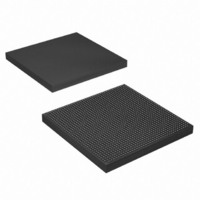
EP4SGX290KF40C3N Altera, EP4SGX290KF40C3N Datasheet - Page 429

EP4SGX290KF40C3N
Manufacturer Part Number
EP4SGX290KF40C3N
Description
IC STRATIX IV GX 290K 1517FBGA
Manufacturer
Altera
Series
Stratix® IV GXr
Datasheets
1.EP4SGX110DF29C3N.pdf
(80 pages)
2.EP4SGX110DF29C3N.pdf
(1154 pages)
3.EP4SGX110DF29C3N.pdf
(432 pages)
4.EP4SGX110DF29C3N.pdf
(22 pages)
5.EP4SGX110DF29C3N.pdf
(30 pages)
6.EP4SGX110DF29C3N.pdf
(72 pages)
Specifications of EP4SGX290KF40C3N
Number Of Logic Elements/cells
291200
Number Of Labs/clbs
11648
Total Ram Bits
17248
Number Of I /o
744
Voltage - Supply
0.87 V ~ 0.93 V
Mounting Type
Surface Mount
Operating Temperature
0°C ~ 85°C
Package / Case
1517-FBGA
Lead Free Status / RoHS Status
Lead free / RoHS Compliant
Number Of Gates
-
Other names
544-2624
Available stocks
Company
Part Number
Manufacturer
Quantity
Price
- EP4SGX110DF29C3N PDF datasheet
- EP4SGX110DF29C3N PDF datasheet #2
- EP4SGX110DF29C3N PDF datasheet #3
- EP4SGX110DF29C3N PDF datasheet #4
- EP4SGX110DF29C3N PDF datasheet #5
- EP4SGX110DF29C3N PDF datasheet #6
- Current page: 429 of 1154
- Download datasheet (32Mb)
Chapter 13: Power Management in Stratix IV Devices
Temperature Sensing Diode
April 2011 Altera Corporation
f
The TSD is a very sensitive circuit that can be influenced by noise coupled from other
traces on the board and possibly within the device package itself, depending on your
device usage. The interfacing device registers’ temperature is based on millivolts
(mV) of difference, as seen at the external TSD pins. Switching the I/O near the TSD
pins can affect the temperature reading. Altera recommends taking temperature
readings during periods of inactivity in the device or use the internal TSD with
built-in ADC circuitry.
The following are board connection guidelines for the TSD external pin connections:
■
■
■
■
■
■
■
■
■
■
■
■
For device specification and connection guidelines, refer to the external temperature
sensor device data sheet from the device manufacturer.
The maximum trace lengths for the TEMPDIODE
less than eight inches.
Route both traces in parallel and place them close to each other with grounded
guard tracks on each side.
Altera recommends 10-mils width and space for both traces.
Route traces through a minimum number of vias and crossunders to minimize the
thermocouple effects.
Ensure that the number of vias are the same on both traces.
Ensure both traces are approximately the same length.
Avoid coupling with toggling signals (for example, clocks and I/O) by having the
GND plane between the diode traces and the high frequency signals.
For high-frequency noise filtering, place an external capacitor (close to the external
chip) between the TEMPDIODE
For Maxim devices, use an external capacitor between 2200 pF to 3300 pF.
Place a 0.1 uF bypass capacitor close to the external device.
You can use internal TSD with built-in ADC circuitry and external TSD at the
same time.
If you only use internal ADC circuitry, the external TSD pins
(TEMPDIODE
external TSD pins are not used.
f
For more information about the TEMPDIODE
connection when you are not using an external TSD, refer to the
Stratix IV GX and Stratix IV E Pin Connection
P
/TEMPDIODE
N
) can connect these pins to GND because the
P
/TEMPDIODE
N
P
trace.
/TEMPDIODE
Guidelines.
P
/TEMPDIODE
Stratix IV Device Handbook Volume 1
N
traces must be
N
pin
13–5
Related parts for EP4SGX290KF40C3N
Image
Part Number
Description
Manufacturer
Datasheet
Request
R

Part Number:
Description:
CYCLONE II STARTER KIT EP2C20N
Manufacturer:
Altera
Datasheet:

Part Number:
Description:
CPLD, EP610 Family, ECMOS Process, 300 Gates, 16 Macro Cells, 16 Reg., 16 User I/Os, 5V Supply, 35 Speed Grade, 24DIP
Manufacturer:
Altera Corporation
Datasheet:

Part Number:
Description:
CPLD, EP610 Family, ECMOS Process, 300 Gates, 16 Macro Cells, 16 Reg., 16 User I/Os, 5V Supply, 15 Speed Grade, 24DIP
Manufacturer:
Altera Corporation
Datasheet:

Part Number:
Description:
Manufacturer:
Altera Corporation
Datasheet:

Part Number:
Description:
CPLD, EP610 Family, ECMOS Process, 300 Gates, 16 Macro Cells, 16 Reg., 16 User I/Os, 5V Supply, 30 Speed Grade, 24DIP
Manufacturer:
Altera Corporation
Datasheet:

Part Number:
Description:
High-performance, low-power erasable programmable logic devices with 8 macrocells, 10ns
Manufacturer:
Altera Corporation
Datasheet:

Part Number:
Description:
High-performance, low-power erasable programmable logic devices with 8 macrocells, 7ns
Manufacturer:
Altera Corporation
Datasheet:

Part Number:
Description:
Classic EPLD
Manufacturer:
Altera Corporation
Datasheet:

Part Number:
Description:
High-performance, low-power erasable programmable logic devices with 8 macrocells, 10ns
Manufacturer:
Altera Corporation
Datasheet:

Part Number:
Description:
Manufacturer:
Altera Corporation
Datasheet:

Part Number:
Description:
Manufacturer:
Altera Corporation
Datasheet:

Part Number:
Description:
Manufacturer:
Altera Corporation
Datasheet:

Part Number:
Description:
CPLD, EP610 Family, ECMOS Process, 300 Gates, 16 Macro Cells, 16 Reg., 16 User I/Os, 5V Supply, 25 Speed Grade, 24DIP
Manufacturer:
Altera Corporation
Datasheet:


