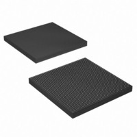
EP4SGX290KF40C3N Altera, EP4SGX290KF40C3N Datasheet - Page 1014

EP4SGX290KF40C3N
Manufacturer Part Number
EP4SGX290KF40C3N
Description
IC STRATIX IV GX 290K 1517FBGA
Manufacturer
Altera
Series
Stratix® IV GXr
Datasheets
1.EP4SGX110DF29C3N.pdf
(80 pages)
2.EP4SGX110DF29C3N.pdf
(1154 pages)
3.EP4SGX110DF29C3N.pdf
(432 pages)
4.EP4SGX110DF29C3N.pdf
(22 pages)
5.EP4SGX110DF29C3N.pdf
(30 pages)
6.EP4SGX110DF29C3N.pdf
(72 pages)
Specifications of EP4SGX290KF40C3N
Number Of Logic Elements/cells
291200
Number Of Labs/clbs
11648
Total Ram Bits
17248
Number Of I /o
744
Voltage - Supply
0.87 V ~ 0.93 V
Mounting Type
Surface Mount
Operating Temperature
0°C ~ 85°C
Package / Case
1517-FBGA
Lead Free Status / RoHS Status
Lead free / RoHS Compliant
Number Of Gates
-
Other names
544-2624
Available stocks
Company
Part Number
Manufacturer
Quantity
Price
- EP4SGX110DF29C3N PDF datasheet
- EP4SGX110DF29C3N PDF datasheet #2
- EP4SGX110DF29C3N PDF datasheet #3
- EP4SGX110DF29C3N PDF datasheet #4
- EP4SGX110DF29C3N PDF datasheet #5
- EP4SGX110DF29C3N PDF datasheet #6
- Current page: 1014 of 1154
- Download datasheet (32Mb)
1–56
Table 1–18. MegaWizard Plug-In Manager Options (SONET/SDH Screen) (Part 2 of 3)
Stratix IV Device Handbook Volume 3
What is the word alignment
pattern?
Flip word alignment pattern bits.
What do you want the byte
ordering to be based on?
Enable run-length violation
checking with a run length of.
Create an rx_syncstatus output
port for pattern detector and word
aligner.
Create an rx_patterndetect
port to indicate pattern detected.
ALTGX Setting
Enter the word alignment pattern. By default, the
pattern that appears in the MegaWizard Plug-In
Manager is '0001010001101111' (16'h146F).
This option is enabled in the MegaWizard Plug-In
Manager by default. This option reverses the order
of the alignment pattern at a bit level to support
MSB-to-LSB transmission in SONET/SDH mode.
The ALTGX MegaWizard Plug-In Manager flips the
bit order of the default word alignment pattern
'0001010001101111 '(16'h146F) and uses the
flipped version '1111011000101000' (16'hF628) as
the word alignment pattern.
This option allows you to trigger the byte ordering
block either on the rising edge of the
rx_syncstatus signal or the user-controlled
rx_enabyteord signal from the FPGA fabric. The
byte ordering block is enabled only in OC-48 mode.
This option creates the output signal rx_rlv.
Enabling this option also activates the run-length
violation circuit. If the number of continuous 1s and
0s exceeds the number that you set in this option,
the run-length violation circuit asserts the rx_rlv
signal. The rx_rlv signal is asynchronous to the
receiver data path and is asserted for a minimum of
two recovered clock cycles in OC-12 and OC-48
modes. Similarly, it is asserted for a minimum of
three recovered clock cycles in the OC-96 mode.
For the OC-12 and OC-48 modes, the run length
limits are 4 to 128 in increments of four. For the
OC-96 mode, the run length limits are 5 to 160 in
increments of five.
This is an output status signal that the word aligner
forwards to the FPGA fabric to indicate that
synchronization has been achieved. This signal is
synchronous with the parallel receiver data on the
rx_dataout port. The signal width is 1 bit, 2 bits,
and 4 bits for a channel width of 8 bits, 16 bits, and
32 bits, respectively.
This is an output status signal that the word aligner
forwards to the FPGA fabric to indicate that the word
alignment pattern programmed has been detected in
the current word boundary. The signal width is 1 bit,
2 bits, and 4 bits for a channel width of 8 bits,
16 bits, and 32 bits, respectively.
Description
Chapter 1: ALTGX Transceiver Setup Guide for Stratix IV Devices
“SONET/SDH Mode” (OC-12,
OC-48, and OC-96) section in
the
Stratix IV Devices
“Byte Ordering Block” section
in the
in Stratix IV Devices
“Programmable Run Length
Violation Detection” section in
the
Stratix IV Devices
Table 1-77 and “Word Aligner”
section in the
Architecture in Stratix IV
Devices
Table 1-33 and “Word Aligner”
section in the
Architecture in Stratix IV
Devices
February 2011 Altera Corporation
Transceiver Architecture in
Transceiver Architecture in
Transceiver Architecture
chapter.
chapter.
Reference
Transceiver
Transceiver
—
Protocol Settings
chapter.
chapter.
chapter.
Related parts for EP4SGX290KF40C3N
Image
Part Number
Description
Manufacturer
Datasheet
Request
R

Part Number:
Description:
CYCLONE II STARTER KIT EP2C20N
Manufacturer:
Altera
Datasheet:

Part Number:
Description:
CPLD, EP610 Family, ECMOS Process, 300 Gates, 16 Macro Cells, 16 Reg., 16 User I/Os, 5V Supply, 35 Speed Grade, 24DIP
Manufacturer:
Altera Corporation
Datasheet:

Part Number:
Description:
CPLD, EP610 Family, ECMOS Process, 300 Gates, 16 Macro Cells, 16 Reg., 16 User I/Os, 5V Supply, 15 Speed Grade, 24DIP
Manufacturer:
Altera Corporation
Datasheet:

Part Number:
Description:
Manufacturer:
Altera Corporation
Datasheet:

Part Number:
Description:
CPLD, EP610 Family, ECMOS Process, 300 Gates, 16 Macro Cells, 16 Reg., 16 User I/Os, 5V Supply, 30 Speed Grade, 24DIP
Manufacturer:
Altera Corporation
Datasheet:

Part Number:
Description:
High-performance, low-power erasable programmable logic devices with 8 macrocells, 10ns
Manufacturer:
Altera Corporation
Datasheet:

Part Number:
Description:
High-performance, low-power erasable programmable logic devices with 8 macrocells, 7ns
Manufacturer:
Altera Corporation
Datasheet:

Part Number:
Description:
Classic EPLD
Manufacturer:
Altera Corporation
Datasheet:

Part Number:
Description:
High-performance, low-power erasable programmable logic devices with 8 macrocells, 10ns
Manufacturer:
Altera Corporation
Datasheet:

Part Number:
Description:
Manufacturer:
Altera Corporation
Datasheet:

Part Number:
Description:
Manufacturer:
Altera Corporation
Datasheet:

Part Number:
Description:
Manufacturer:
Altera Corporation
Datasheet:

Part Number:
Description:
CPLD, EP610 Family, ECMOS Process, 300 Gates, 16 Macro Cells, 16 Reg., 16 User I/Os, 5V Supply, 25 Speed Grade, 24DIP
Manufacturer:
Altera Corporation
Datasheet:


