OM13005,598 NXP Semiconductors, OM13005,598 Datasheet - Page 87
OM13005,598
Manufacturer Part Number
OM13005,598
Description
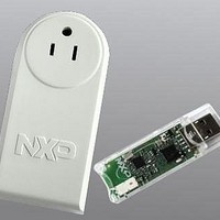
BOARD EVAL EM773 METER US PLUG
Manufacturer
NXP Semiconductors
Type
Other Power Managementr
Specifications of OM13005,598
Design Resources
Plug Meter Schematics, Gerber Files USB Dongle Schematics, Gerber Files
Main Purpose
Power Management, Energy/Power Meter
Embedded
Yes, MCU, 32-Bit
Utilized Ic / Part
EM773FHN33,551
Interface Type
USB
Maximum Operating Temperature
+ 150 C
Operating Supply Voltage
1.8 V to 3.6 V
Product
Power Management Development Tools
Lead Free Status / RoHS Status
Lead free / RoHS Compliant
Primary Attributes
-
Secondary Attributes
-
Lead Free Status / Rohs Status
Lead free / RoHS Compliant
For Use With/related Products
EM773, OL2381
Other names
568-6680


NXP Semiconductors
UM10415
User manual
9.6.14 Auto-baud modes
The U0ACR AutoRestart bit can be used to automatically restart baud rate measurement
if a time-out occurs (the rate measurement counter overflows). If this bit is set, the rate
measurement will restart at the next falling edge of the UART Rx pin.
The auto-baud function can generate two interrupts.
The auto-baud interrupts have to be cleared by setting the corresponding U0ACR
ABTOIntClr and ABEOIntEn bits.
The fractional baud rate generator must be disabled (DIVADDVAL = 0) during auto-baud.
Also, when auto-baud is used, any write to U0DLM and U0DLL registers should be done
before U0ACR register write. The minimum and the maximum baud rates supported by
UART are function of UART_PCLK, number of data bits, stop bits and parity bits.
When the software is expecting an ”AT" command, it configures the UART with the
expected character format and sets the U0ACR Start bit. The initial values in the divisor
latches U0DLM and U0DLM don‘t care. Because of the ”A" or ”a" ASCII coding
(”A" = 0x41, ”a" = 0x61), the UART Rx pin sensed start bit and the LSB of the expected
character are delimited by two falling edges. When the U0ACR Start bit is set, the
auto-baud protocol will execute the following phases:
1. On U0ACR Start bit setting, the baud rate measurement counter is reset and the
2. A falling edge on UART Rx pin triggers the beginning of the start bit. The rate
3. During the receipt of the start bit, 16 pulses are generated on the RSR baud input with
4. During the receipt of the start bit (and the character LSB for Mode = 0), the rate
5. If Mode = 0, the rate counter will stop on next falling edge of the UART Rx pin. If
•
•
ratemin
The U0IIR ABTOInt interrupt will get set if the interrupt is enabled (U0IER ABToIntEn
is set and the auto-baud rate measurement counter overflows).
The U0IIR ABEOInt interrupt will get set if the interrupt is enabled (U0IER ABEOIntEn
is set and the auto-baud has completed successfully).
UART U0RSR is reset. The U0RSR baud rate is switched to the highest rate.
measuring counter will start counting UART_PCLK cycles.
the frequency of the UART input clock, guaranteeing the start bit is stored in the
U0RSR.
counter will continue incrementing with the pre-scaled UART input clock
(UART_PCLK).
Mode = 1, the rate counter will stop on the next rising edge of the UART Rx pin.
=
2 P
------------------------ -
16 2 15
All information provided in this document is subject to legal disclaimers.
× CLK
×
Rev. 1 — 10 September 2010
Chapter 9: EM773 Universal Asynchronous Transmitter (UART)
≤
UART baudrate
≤
----------------------------------------------------------------------------------------------------------- -
16
×
(
2
+
databits
PCLK
+
paritybits
+
stopbits
UM10415
© NXP B.V. 2010. All rights reserved.
)
=
ratemax
87 of 310
(2)
Related parts for OM13005,598
Image
Part Number
Description
Manufacturer
Datasheet
Request
R

Part Number:
Description:
NXP Semiconductors designed the LPC2420/2460 microcontroller around a 16-bit/32-bitARM7TDMI-S CPU core with real-time debug interfaces that include both JTAG andembedded trace
Manufacturer:
NXP Semiconductors
Datasheet:

Part Number:
Description:
NXP Semiconductors designed the LPC2458 microcontroller around a 16-bit/32-bitARM7TDMI-S CPU core with real-time debug interfaces that include both JTAG andembedded trace
Manufacturer:
NXP Semiconductors
Datasheet:
Part Number:
Description:
NXP Semiconductors designed the LPC2468 microcontroller around a 16-bit/32-bitARM7TDMI-S CPU core with real-time debug interfaces that include both JTAG andembedded trace
Manufacturer:
NXP Semiconductors
Datasheet:
Part Number:
Description:
NXP Semiconductors designed the LPC2470 microcontroller, powered by theARM7TDMI-S core, to be a highly integrated microcontroller for a wide range ofapplications that require advanced communications and high quality graphic displays
Manufacturer:
NXP Semiconductors
Datasheet:
Part Number:
Description:
NXP Semiconductors designed the LPC2478 microcontroller, powered by theARM7TDMI-S core, to be a highly integrated microcontroller for a wide range ofapplications that require advanced communications and high quality graphic displays
Manufacturer:
NXP Semiconductors
Datasheet:
Part Number:
Description:
The Philips Semiconductors XA (eXtended Architecture) family of 16-bit single-chip microcontrollers is powerful enough to easily handle the requirements of high performance embedded applications, yet inexpensive enough to compete in the market for hi
Manufacturer:
NXP Semiconductors
Datasheet:
Part Number:
Description:
The XA-S3 device is a member of Philips Semiconductors? XA(eXtended Architecture) family of high performance 16-bitsingle-chip microcontrollers
Manufacturer:
NXP Semiconductors
Datasheet:

Part Number:
Description:
The NXP BlueStreak LH75401/LH75411 family consists of two low-cost 16/32-bit System-on-Chip (SoC) devices
Manufacturer:
NXP Semiconductors
Datasheet:
Part Number:
Description:
The NXP LPC3130/3131 combine an 180 MHz ARM926EJ-S CPU core, high-speed USB2
Manufacturer:
NXP Semiconductors
Datasheet:
Part Number:
Description:
The NXP LPC3141 combine a 270 MHz ARM926EJ-S CPU core, High-speed USB 2
Manufacturer:
NXP Semiconductors
Part Number:
Description:
The NXP LPC3143 combine a 270 MHz ARM926EJ-S CPU core, High-speed USB 2
Manufacturer:
NXP Semiconductors

Part Number:
Description:
The NXP LPC3152 combines an 180 MHz ARM926EJ-S CPU core, High-speed USB 2
Manufacturer:
NXP Semiconductors
Part Number:
Description:
The NXP LPC3154 combines an 180 MHz ARM926EJ-S CPU core, High-speed USB 2
Manufacturer:
NXP Semiconductors

Part Number:
Description:
Standard level N-channel enhancement mode Field-Effect Transistor (FET) in a plastic package using NXP High-Performance Automotive (HPA) TrenchMOS technology
Manufacturer:
NXP Semiconductors
Datasheet: