OM13005,598 NXP Semiconductors, OM13005,598 Datasheet - Page 113
OM13005,598
Manufacturer Part Number
OM13005,598
Description
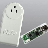
BOARD EVAL EM773 METER US PLUG
Manufacturer
NXP Semiconductors
Type
Other Power Managementr
Specifications of OM13005,598
Design Resources
Plug Meter Schematics, Gerber Files USB Dongle Schematics, Gerber Files
Main Purpose
Power Management, Energy/Power Meter
Embedded
Yes, MCU, 32-Bit
Utilized Ic / Part
EM773FHN33,551
Interface Type
USB
Maximum Operating Temperature
+ 150 C
Operating Supply Voltage
1.8 V to 3.6 V
Product
Power Management Development Tools
Lead Free Status / RoHS Status
Lead free / RoHS Compliant
Primary Attributes
-
Secondary Attributes
-
Lead Free Status / Rohs Status
Lead free / RoHS Compliant
For Use With/related Products
EM773, OL2381
Other names
568-6680


NXP Semiconductors
UM10415
User manual
10.10.7 Serial clock generator
The synchronization logic will synchronize the serial clock generator with the clock pulses
on the SCL line from another device. If two or more master devices generate clock pulses,
the “mark” duration is determined by the device that generates the shortest “marks,” and
the “space” duration is determined by the device that generates the longest “spaces”.
Figure 22
A slave may stretch the space duration to slow down the bus master. The space duration
may also be stretched for handshaking purposes. This can be done after each bit or after
a complete byte transfer. the I
been transmitted or received and the acknowledge bit has been transferred. The serial
interrupt flag (SI) is set, and the stretching continues until the serial interrupt flag is
cleared.
This programmable clock pulse generator provides the SCL clock pulses when the I
block is in the master transmitter or master receiver mode. It is switched off when the I
block is in a slave mode. The I
Fig 21. Arbitration procedure
Fig 22. Serial clock synchronization
(1) Another device transmits serial data.
(2) Another device overrules a logic (dotted line) transmitted this I
(3) This I
(1) Another device pulls the SCL line low before this I
(2) Another device continues to pull the SCL line low after this I
(3) The SCL line is released , and the clock generator begins timing the HIGH time.
low. Arbitration is lost, and this I
transmitted. This I
the new master once it has won arbitration.
device effectively determines the (shorter) HIGH period.
released SCL. The I
effectively determines the (longer) LOW period.
SDA line
SCL line
shows the synchronization procedure.
SDA line
SCL line
2
C is in Slave Receiver mode but still generates clock pulses until the current byte has been
All information provided in this document is subject to legal disclaimers.
Rev. 1 — 10 September 2010
2
C will not generate clock pulses for the next byte. Data on SDA originates from
2
C clock generator is forced to wait until SCL goes HIGH. The other device
(1)
1
period
high
2
C block will stretch the SCL space duration after a byte has
2
C output clock frequency and duty cycle is programmable
(1)
(1)
2
2
C enters Slave Receiver mode.
period
low
(2)
3
(2)
(3)
4
2
C has timed a complete high time. The other
Chapter 10: EM773 I2C-bus interface
(1)
2
C has timed a complete low time and
(3)
2
C master by pulling the SDA line
8
UM10415
© NXP B.V. 2010. All rights reserved.
ACK
9
113 of 310
2
C
2
C
Related parts for OM13005,598
Image
Part Number
Description
Manufacturer
Datasheet
Request
R

Part Number:
Description:
NXP Semiconductors designed the LPC2420/2460 microcontroller around a 16-bit/32-bitARM7TDMI-S CPU core with real-time debug interfaces that include both JTAG andembedded trace
Manufacturer:
NXP Semiconductors
Datasheet:

Part Number:
Description:
NXP Semiconductors designed the LPC2458 microcontroller around a 16-bit/32-bitARM7TDMI-S CPU core with real-time debug interfaces that include both JTAG andembedded trace
Manufacturer:
NXP Semiconductors
Datasheet:
Part Number:
Description:
NXP Semiconductors designed the LPC2468 microcontroller around a 16-bit/32-bitARM7TDMI-S CPU core with real-time debug interfaces that include both JTAG andembedded trace
Manufacturer:
NXP Semiconductors
Datasheet:
Part Number:
Description:
NXP Semiconductors designed the LPC2470 microcontroller, powered by theARM7TDMI-S core, to be a highly integrated microcontroller for a wide range ofapplications that require advanced communications and high quality graphic displays
Manufacturer:
NXP Semiconductors
Datasheet:
Part Number:
Description:
NXP Semiconductors designed the LPC2478 microcontroller, powered by theARM7TDMI-S core, to be a highly integrated microcontroller for a wide range ofapplications that require advanced communications and high quality graphic displays
Manufacturer:
NXP Semiconductors
Datasheet:
Part Number:
Description:
The Philips Semiconductors XA (eXtended Architecture) family of 16-bit single-chip microcontrollers is powerful enough to easily handle the requirements of high performance embedded applications, yet inexpensive enough to compete in the market for hi
Manufacturer:
NXP Semiconductors
Datasheet:
Part Number:
Description:
The XA-S3 device is a member of Philips Semiconductors? XA(eXtended Architecture) family of high performance 16-bitsingle-chip microcontrollers
Manufacturer:
NXP Semiconductors
Datasheet:

Part Number:
Description:
The NXP BlueStreak LH75401/LH75411 family consists of two low-cost 16/32-bit System-on-Chip (SoC) devices
Manufacturer:
NXP Semiconductors
Datasheet:
Part Number:
Description:
The NXP LPC3130/3131 combine an 180 MHz ARM926EJ-S CPU core, high-speed USB2
Manufacturer:
NXP Semiconductors
Datasheet:
Part Number:
Description:
The NXP LPC3141 combine a 270 MHz ARM926EJ-S CPU core, High-speed USB 2
Manufacturer:
NXP Semiconductors
Part Number:
Description:
The NXP LPC3143 combine a 270 MHz ARM926EJ-S CPU core, High-speed USB 2
Manufacturer:
NXP Semiconductors

Part Number:
Description:
The NXP LPC3152 combines an 180 MHz ARM926EJ-S CPU core, High-speed USB 2
Manufacturer:
NXP Semiconductors
Part Number:
Description:
The NXP LPC3154 combines an 180 MHz ARM926EJ-S CPU core, High-speed USB 2
Manufacturer:
NXP Semiconductors

Part Number:
Description:
Standard level N-channel enhancement mode Field-Effect Transistor (FET) in a plastic package using NXP High-Performance Automotive (HPA) TrenchMOS technology
Manufacturer:
NXP Semiconductors
Datasheet: