OM13005,598 NXP Semiconductors, OM13005,598 Datasheet - Page 306
OM13005,598
Manufacturer Part Number
OM13005,598
Description
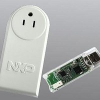
BOARD EVAL EM773 METER US PLUG
Manufacturer
NXP Semiconductors
Type
Other Power Managementr
Specifications of OM13005,598
Design Resources
Plug Meter Schematics, Gerber Files USB Dongle Schematics, Gerber Files
Main Purpose
Power Management, Energy/Power Meter
Embedded
Yes, MCU, 32-Bit
Utilized Ic / Part
EM773FHN33,551
Interface Type
USB
Maximum Operating Temperature
+ 150 C
Operating Supply Voltage
1.8 V to 3.6 V
Product
Power Management Development Tools
Lead Free Status / RoHS Status
Lead free / RoHS Compliant
Primary Attributes
-
Secondary Attributes
-
Lead Free Status / Rohs Status
Lead free / RoHS Compliant
For Use With/related Products
EM773, OL2381
Other names
568-6680


NXP Semiconductors
13.8.9
13.8.10
13.8.11
Chapter 14: EM773 WatchDog Timer (WDT)
14.1
14.2
14.3
14.4
14.5
14.6
14.7
Chapter 15: EM773 System tick timer
15.1
15.2
15.3
15.4
15.5
15.6
Chapter 16: EM773 Metrology engine
16.1
16.2
16.3
16.4
16.4.1
16.4.2
16.4.3
16.5
16.5.1
16.5.2
Chapter 17: EM773 Metrology engine interface
17.1
17.2
17.2.1
17.2.2
17.2.3
17.2.4
17.2.5
Chapter 18: EM773 Flash memory programming firmware
18.1
18.2
UM10415
User manual
How to read this chapter . . . . . . . . . . . . . . . . 178
Basic configuration . . . . . . . . . . . . . . . . . . . . 178
Features . . . . . . . . . . . . . . . . . . . . . . . . . . . . . 178
Applications . . . . . . . . . . . . . . . . . . . . . . . . . . 178
Description . . . . . . . . . . . . . . . . . . . . . . . . . . . 179
Clocking and power control . . . . . . . . . . . . . 179
Register description . . . . . . . . . . . . . . . . . . . 179
How to read this chapter . . . . . . . . . . . . . . . . 183
Basic configuration . . . . . . . . . . . . . . . . . . . . 183
Features . . . . . . . . . . . . . . . . . . . . . . . . . . . . . 183
Description . . . . . . . . . . . . . . . . . . . . . . . . . . . 183
Operation . . . . . . . . . . . . . . . . . . . . . . . . . . . . 184
Register description . . . . . . . . . . . . . . . . . . . 184
How to read this chapter . . . . . . . . . . . . . . . . 187
Introduction . . . . . . . . . . . . . . . . . . . . . . . . . . 187
Features . . . . . . . . . . . . . . . . . . . . . . . . . . . . . 188
Pin description . . . . . . . . . . . . . . . . . . . . . . . . 188
Output definitions . . . . . . . . . . . . . . . . . . . . . 189
How to read this chapter . . . . . . . . . . . . . . . . 197
Metrology driver interface. . . . . . . . . . . . . . . 197
Features . . . . . . . . . . . . . . . . . . . . . . . . . . . . . 201
General description . . . . . . . . . . . . . . . . . . . . 201
Capture Register (TMR32B0CR0 - address
0x4001 402C) . . . . . . . . . . . . . . . . . . . . . . . . 172
External Match Register (TMR32B0EMR and
TMR32B1EMR) . . . . . . . . . . . . . . . . . . . . . . 172
Count Control Register (TMR32B0CTCR and
TMR32B1TCR) . . . . . . . . . . . . . . . . . . . . . . . 173
I_HIGHGAIN . . . . . . . . . . . . . . . . . . . . . . . . . 188
I_LOWGAIN . . . . . . . . . . . . . . . . . . . . . . . . . 188
VOLTAGE . . . . . . . . . . . . . . . . . . . . . . . . . . . 189
Output for sinusoidal and non-sinusoidal voltage
and sinusoidal and non-sinusoidal current . . 189
Additional output for sinusoidal voltage and
sinusoidal and non-sinusoidal current . . . . . 190
Metrology Engine initialization . . . . . . . . . . . 197
Metrology Engine interrupt handler . . . . . . . 197
Metrology Engine set ranges . . . . . . . . . . . . 197
Metrology Engine start . . . . . . . . . . . . . . . . . 198
Metrology Engine stop . . . . . . . . . . . . . . . . . 198
All information provided in this document is subject to legal disclaimers.
Rev. 1 — 10 September 2010
13.8.12
13.8.13
13.9
13.10
14.7.1
14.7.2
14.7.3
14.7.4
14.8
15.6.1
15.6.2
15.6.3
15.6.4
15.7
16.6
16.6.1
16.6.1.1
16.6.1.2
16.6.1.3
16.6.1.4
16.6.1.5
16.6.2
16.6.2.1
16.6.2.2
16.6.2.3
16.6.2.4
16.6.2.5
17.2.6
17.2.7
17.3
17.4
17.4.1
17.4.2
18.2.1
18.2.2
Chapter 21: EM773 Supplementary information
Example timer operation . . . . . . . . . . . . . . . 176
Architecture . . . . . . . . . . . . . . . . . . . . . . . . . . 177
Block diagram . . . . . . . . . . . . . . . . . . . . . . . . 182
Example timer calculations . . . . . . . . . . . . . 186
Operation . . . . . . . . . . . . . . . . . . . . . . . . . . . . 192
Calling the metrology driver . . . . . . . . . . . . 198
Metrology driver structure definitions . . . . 199
PWM Control Register (TMR32B0PWMC and
TMR32B1PWMC) . . . . . . . . . . . . . . . . . . . . 174
Rules for single edge controlled PWM outputs . .
175
Watchdog Mode register (WDMOD -
0x4000 0000) . . . . . . . . . . . . . . . . . . . . . . . . 180
Watchdog Timer Constant register (WDTC -
0x4000 4004) . . . . . . . . . . . . . . . . . . . . . . . . 181
Watchdog Feed register (WDFEED -
0x4000 4008) . . . . . . . . . . . . . . . . . . . . . . . . 181
Watchdog Timer Value register (WDTV -
0x4000 400C) . . . . . . . . . . . . . . . . . . . . . . . 181
System Timer Control and status register . . 185
System Timer Reload value register . . . . . . 185
System Timer Current value register . . . . . 185
System Timer Calibration value register
(SYST_CALIB - 0xE000 E01C) . . . . . . . . . . 185
Example (system clock = 48 MHz). . . . . . . . . 186
Configuration data . . . . . . . . . . . . . . . . . . . . 192
Voltage measurement input range Vpp . . . . 192
Current measurement input range I1pp . . . . 192
Current measurement input range I2pp . . . . 193
Phase error correction angle DeltaPhi1 . . . . 193
Phase error correction angle DeltaPhi2 . . . . 193
Calibration procedure. . . . . . . . . . . . . . . . . . 194
Vpp calibration . . . . . . . . . . . . . . . . . . . . . . . 194
I1pp calibration. . . . . . . . . . . . . . . . . . . . . . . 195
I2pp calibration. . . . . . . . . . . . . . . . . . . . . . . 195
DeltaPhi1 calibration . . . . . . . . . . . . . . . . . . 196
DeltaPhi2 calibration . . . . . . . . . . . . . . . . . . 196
Metrology Engine read data . . . . . . . . . . . . . 198
Metrology Engine get gain channel . . . . . . . 198
Metrology ranges . . . . . . . . . . . . . . . . . . . . . 199
Metrology result . . . . . . . . . . . . . . . . . . . . . . 199
Boot loader. . . . . . . . . . . . . . . . . . . . . . . . . . 201
Memory map after any reset . . . . . . . . . . . . 201
UM10415
© NXP B.V. 2010. All rights reserved.
306 of 310
Related parts for OM13005,598
Image
Part Number
Description
Manufacturer
Datasheet
Request
R

Part Number:
Description:
NXP Semiconductors designed the LPC2420/2460 microcontroller around a 16-bit/32-bitARM7TDMI-S CPU core with real-time debug interfaces that include both JTAG andembedded trace
Manufacturer:
NXP Semiconductors
Datasheet:

Part Number:
Description:
NXP Semiconductors designed the LPC2458 microcontroller around a 16-bit/32-bitARM7TDMI-S CPU core with real-time debug interfaces that include both JTAG andembedded trace
Manufacturer:
NXP Semiconductors
Datasheet:
Part Number:
Description:
NXP Semiconductors designed the LPC2468 microcontroller around a 16-bit/32-bitARM7TDMI-S CPU core with real-time debug interfaces that include both JTAG andembedded trace
Manufacturer:
NXP Semiconductors
Datasheet:
Part Number:
Description:
NXP Semiconductors designed the LPC2470 microcontroller, powered by theARM7TDMI-S core, to be a highly integrated microcontroller for a wide range ofapplications that require advanced communications and high quality graphic displays
Manufacturer:
NXP Semiconductors
Datasheet:
Part Number:
Description:
NXP Semiconductors designed the LPC2478 microcontroller, powered by theARM7TDMI-S core, to be a highly integrated microcontroller for a wide range ofapplications that require advanced communications and high quality graphic displays
Manufacturer:
NXP Semiconductors
Datasheet:
Part Number:
Description:
The Philips Semiconductors XA (eXtended Architecture) family of 16-bit single-chip microcontrollers is powerful enough to easily handle the requirements of high performance embedded applications, yet inexpensive enough to compete in the market for hi
Manufacturer:
NXP Semiconductors
Datasheet:
Part Number:
Description:
The XA-S3 device is a member of Philips Semiconductors? XA(eXtended Architecture) family of high performance 16-bitsingle-chip microcontrollers
Manufacturer:
NXP Semiconductors
Datasheet:

Part Number:
Description:
The NXP BlueStreak LH75401/LH75411 family consists of two low-cost 16/32-bit System-on-Chip (SoC) devices
Manufacturer:
NXP Semiconductors
Datasheet:
Part Number:
Description:
The NXP LPC3130/3131 combine an 180 MHz ARM926EJ-S CPU core, high-speed USB2
Manufacturer:
NXP Semiconductors
Datasheet:
Part Number:
Description:
The NXP LPC3141 combine a 270 MHz ARM926EJ-S CPU core, High-speed USB 2
Manufacturer:
NXP Semiconductors
Part Number:
Description:
The NXP LPC3143 combine a 270 MHz ARM926EJ-S CPU core, High-speed USB 2
Manufacturer:
NXP Semiconductors

Part Number:
Description:
The NXP LPC3152 combines an 180 MHz ARM926EJ-S CPU core, High-speed USB 2
Manufacturer:
NXP Semiconductors
Part Number:
Description:
The NXP LPC3154 combines an 180 MHz ARM926EJ-S CPU core, High-speed USB 2
Manufacturer:
NXP Semiconductors

Part Number:
Description:
Standard level N-channel enhancement mode Field-Effect Transistor (FET) in a plastic package using NXP High-Performance Automotive (HPA) TrenchMOS technology
Manufacturer:
NXP Semiconductors
Datasheet: