OM13005,598 NXP Semiconductors, OM13005,598 Datasheet - Page 132
OM13005,598
Manufacturer Part Number
OM13005,598
Description
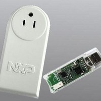
BOARD EVAL EM773 METER US PLUG
Manufacturer
NXP Semiconductors
Type
Other Power Managementr
Specifications of OM13005,598
Design Resources
Plug Meter Schematics, Gerber Files USB Dongle Schematics, Gerber Files
Main Purpose
Power Management, Energy/Power Meter
Embedded
Yes, MCU, 32-Bit
Utilized Ic / Part
EM773FHN33,551
Interface Type
USB
Maximum Operating Temperature
+ 150 C
Operating Supply Voltage
1.8 V to 3.6 V
Product
Power Management Development Tools
Lead Free Status / RoHS Status
Lead free / RoHS Compliant
Primary Attributes
-
Secondary Attributes
-
Lead Free Status / Rohs Status
Lead free / RoHS Compliant
For Use With/related Products
EM773, OL2381
Other names
568-6680


NXP Semiconductors
10.12 Software example
UM10415
User manual
10.11.10 The state service routines
10.11.11 Adapting state services to an application
10.12.1 Initialization routine
10.12.2 Start Master Transmit function
10.11.8 Initialization
10.11.9 I
In the initialization example, the I
For each mode, a buffer is used for transmission and reception. The initialization routine
performs the following functions:
The I
Call. If the General Call or the own slave address is detected, an interrupt is requested
and I2STAT is loaded with the appropriate state information.
When the I
the 26 state services to be executed.
Each state routine is part of the I
The state service examples show the typical actions that must be performed in response
to the 26 I
associated state services can be omitted, as long as care is taken that the those states
can never occur.
In an application, it may be desirable to implement some kind of timeout during I
operations, in order to trap an inoperative bus or a lost service routine.
Example to initialize I
Begin a Master Transmit operation by setting up the buffer, pointer, and data count, then
initiating a START.
2
1. Load I2ADR with own Slave Address, enable General Call recognition if needed.
2. Enable I
3. Write 0x44 to I2CONSET to set the I2EN and AA bits, enabling Slave functions. For
1. Initialize Master data counter.
•
•
•
C interrupt service
I2ADR is loaded with the part’s own slave address and the General Call bit (GC)
The I
The slave mode is enabled by simultaneously setting the I2EN and AA bits in I2CON
and the serial clock frequency (for master modes) is defined by is defined by loading
the
program.
Master only functions, write 0x40 to I2CONSET.
2
C hardware now begins checking the I
I2SCLH and I2SCLL registers
2
2
C interrupt enable and interrupt priority bits are set
C state codes. If one or more of the four I
2
C interrupt is entered, I2STAT contains a status code which identifies one of
2
C interrupt.
All information provided in this document is subject to legal disclaimers.
Rev. 1 — 10 September 2010
2
C Interface as a Slave and/or Master.
2
2
C interrupt routine and handles one of the 26 states.
C block is enabled for both master and slave modes.
. The master routines must be started in the main
2
C-bus for its own slave address and General
Chapter 10: EM773 I2C-bus interface
2
C operating modes are not used, the
UM10415
© NXP B.V. 2010. All rights reserved.
2
132 of 310
C
Related parts for OM13005,598
Image
Part Number
Description
Manufacturer
Datasheet
Request
R

Part Number:
Description:
NXP Semiconductors designed the LPC2420/2460 microcontroller around a 16-bit/32-bitARM7TDMI-S CPU core with real-time debug interfaces that include both JTAG andembedded trace
Manufacturer:
NXP Semiconductors
Datasheet:

Part Number:
Description:
NXP Semiconductors designed the LPC2458 microcontroller around a 16-bit/32-bitARM7TDMI-S CPU core with real-time debug interfaces that include both JTAG andembedded trace
Manufacturer:
NXP Semiconductors
Datasheet:
Part Number:
Description:
NXP Semiconductors designed the LPC2468 microcontroller around a 16-bit/32-bitARM7TDMI-S CPU core with real-time debug interfaces that include both JTAG andembedded trace
Manufacturer:
NXP Semiconductors
Datasheet:
Part Number:
Description:
NXP Semiconductors designed the LPC2470 microcontroller, powered by theARM7TDMI-S core, to be a highly integrated microcontroller for a wide range ofapplications that require advanced communications and high quality graphic displays
Manufacturer:
NXP Semiconductors
Datasheet:
Part Number:
Description:
NXP Semiconductors designed the LPC2478 microcontroller, powered by theARM7TDMI-S core, to be a highly integrated microcontroller for a wide range ofapplications that require advanced communications and high quality graphic displays
Manufacturer:
NXP Semiconductors
Datasheet:
Part Number:
Description:
The Philips Semiconductors XA (eXtended Architecture) family of 16-bit single-chip microcontrollers is powerful enough to easily handle the requirements of high performance embedded applications, yet inexpensive enough to compete in the market for hi
Manufacturer:
NXP Semiconductors
Datasheet:
Part Number:
Description:
The XA-S3 device is a member of Philips Semiconductors? XA(eXtended Architecture) family of high performance 16-bitsingle-chip microcontrollers
Manufacturer:
NXP Semiconductors
Datasheet:

Part Number:
Description:
The NXP BlueStreak LH75401/LH75411 family consists of two low-cost 16/32-bit System-on-Chip (SoC) devices
Manufacturer:
NXP Semiconductors
Datasheet:
Part Number:
Description:
The NXP LPC3130/3131 combine an 180 MHz ARM926EJ-S CPU core, high-speed USB2
Manufacturer:
NXP Semiconductors
Datasheet:
Part Number:
Description:
The NXP LPC3141 combine a 270 MHz ARM926EJ-S CPU core, High-speed USB 2
Manufacturer:
NXP Semiconductors
Part Number:
Description:
The NXP LPC3143 combine a 270 MHz ARM926EJ-S CPU core, High-speed USB 2
Manufacturer:
NXP Semiconductors

Part Number:
Description:
The NXP LPC3152 combines an 180 MHz ARM926EJ-S CPU core, High-speed USB 2
Manufacturer:
NXP Semiconductors
Part Number:
Description:
The NXP LPC3154 combines an 180 MHz ARM926EJ-S CPU core, High-speed USB 2
Manufacturer:
NXP Semiconductors

Part Number:
Description:
Standard level N-channel enhancement mode Field-Effect Transistor (FET) in a plastic package using NXP High-Performance Automotive (HPA) TrenchMOS technology
Manufacturer:
NXP Semiconductors
Datasheet: