OM13005,598 NXP Semiconductors, OM13005,598 Datasheet - Page 37
OM13005,598
Manufacturer Part Number
OM13005,598
Description
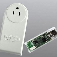
BOARD EVAL EM773 METER US PLUG
Manufacturer
NXP Semiconductors
Type
Other Power Managementr
Specifications of OM13005,598
Design Resources
Plug Meter Schematics, Gerber Files USB Dongle Schematics, Gerber Files
Main Purpose
Power Management, Energy/Power Meter
Embedded
Yes, MCU, 32-Bit
Utilized Ic / Part
EM773FHN33,551
Interface Type
USB
Maximum Operating Temperature
+ 150 C
Operating Supply Voltage
1.8 V to 3.6 V
Product
Power Management Development Tools
Lead Free Status / RoHS Status
Lead free / RoHS Compliant
Primary Attributes
-
Secondary Attributes
-
Lead Free Status / Rohs Status
Lead free / RoHS Compliant
For Use With/related Products
EM773, OL2381
Other names
568-6680


NXP Semiconductors
UM10415
User manual
3.9.4.1 Normal mode
3.9.4.2 Power-down mode
Table 39.
In normal mode the post divider is enabled, giving a 50% duty cycle clock with the
following frequency relations:
To select the appropriate values for M and P, it is recommended to follow these steps:
Table 40
SYSPLLCTRL register
system clock divider SYSAHBCLKDIV is set to one (see
Table 40.
In this mode, the internal current reference will be turned off, the oscillator and the
phase-frequency detector will be stopped and the dividers will enter a reset state. While in
Power-down mode, the lock output will be low, to indicate that the PLL is not in lock. When
the Power-down mode is terminated by setting the SYSPLL_PD bit to zero in the
Power-down configuration register
and will make the lock signal HIGH once it has regained lock on the input clock.
Parameter
FCLKIN
FCCO
FCLKOUT
P
M
PLL input
clock
sys_pllclkin
(Fclkin)
12 MHz
12 MHz
12 MHz
1. Specify the input clock frequency Fclkin.
2. Calculate M to obtain the desired output frequency Fclkout with M = F
3. Find a value so that FCCO = 2 × P × F
4. Verify that all frequencies and divider values conform to the limits specified in
shows how to configure the PLL for a 12 MHz crystal oscillator using the
PLL frequency parameters
PLL configuration examples
All information provided in this document is subject to legal disclaimers.
Main clock
(Fclkout)
48 MHz
36 MHz
24 MHz
System PLL
Frequency of sys_pllclkin (input clock to the system PLL) from the
SYSPLLCLKSEL multiplexer (see
Frequency of the Current Controlled Oscillator (CCO); 156 to 320 MHz.
Frequency of sys_pllclkout
System PLL post divider ratio; PSEL bits in SYSPLLCTRL (see
System PLL feedback divider register; MSEL bits in SYSPLLCTRL (see
Section
Fclkout
Rev. 1 — 10 September 2010
(Table
3.4.3).
=
6). The main clock is equivalent to the system clock if the
00011
00010
00001
MSEL bits
Table 6
M
×
(Table
Fclkin
37), the PLL will resume its normal operation
clkout
M divider
value
4
3
2
=
(
Chapter 3: EM773 System configuration
.
FCCO
Section
PSEL bits
Table 6
01
10
10
)
⁄
(
3.4.9).
Table
2
×
P
)
16).
P divider
value
2
4
4
UM10415
© NXP B.V. 2010. All rights reserved.
clkout
Section
FCCO
frequency
192 MHz
288 MHz
192 MHz
/ F
clkin
Table
3.4.3).
37 of 13
.
(1)
6.
Related parts for OM13005,598
Image
Part Number
Description
Manufacturer
Datasheet
Request
R

Part Number:
Description:
NXP Semiconductors designed the LPC2420/2460 microcontroller around a 16-bit/32-bitARM7TDMI-S CPU core with real-time debug interfaces that include both JTAG andembedded trace
Manufacturer:
NXP Semiconductors
Datasheet:

Part Number:
Description:
NXP Semiconductors designed the LPC2458 microcontroller around a 16-bit/32-bitARM7TDMI-S CPU core with real-time debug interfaces that include both JTAG andembedded trace
Manufacturer:
NXP Semiconductors
Datasheet:
Part Number:
Description:
NXP Semiconductors designed the LPC2468 microcontroller around a 16-bit/32-bitARM7TDMI-S CPU core with real-time debug interfaces that include both JTAG andembedded trace
Manufacturer:
NXP Semiconductors
Datasheet:
Part Number:
Description:
NXP Semiconductors designed the LPC2470 microcontroller, powered by theARM7TDMI-S core, to be a highly integrated microcontroller for a wide range ofapplications that require advanced communications and high quality graphic displays
Manufacturer:
NXP Semiconductors
Datasheet:
Part Number:
Description:
NXP Semiconductors designed the LPC2478 microcontroller, powered by theARM7TDMI-S core, to be a highly integrated microcontroller for a wide range ofapplications that require advanced communications and high quality graphic displays
Manufacturer:
NXP Semiconductors
Datasheet:
Part Number:
Description:
The Philips Semiconductors XA (eXtended Architecture) family of 16-bit single-chip microcontrollers is powerful enough to easily handle the requirements of high performance embedded applications, yet inexpensive enough to compete in the market for hi
Manufacturer:
NXP Semiconductors
Datasheet:
Part Number:
Description:
The XA-S3 device is a member of Philips Semiconductors? XA(eXtended Architecture) family of high performance 16-bitsingle-chip microcontrollers
Manufacturer:
NXP Semiconductors
Datasheet:

Part Number:
Description:
The NXP BlueStreak LH75401/LH75411 family consists of two low-cost 16/32-bit System-on-Chip (SoC) devices
Manufacturer:
NXP Semiconductors
Datasheet:
Part Number:
Description:
The NXP LPC3130/3131 combine an 180 MHz ARM926EJ-S CPU core, high-speed USB2
Manufacturer:
NXP Semiconductors
Datasheet:
Part Number:
Description:
The NXP LPC3141 combine a 270 MHz ARM926EJ-S CPU core, High-speed USB 2
Manufacturer:
NXP Semiconductors
Part Number:
Description:
The NXP LPC3143 combine a 270 MHz ARM926EJ-S CPU core, High-speed USB 2
Manufacturer:
NXP Semiconductors

Part Number:
Description:
The NXP LPC3152 combines an 180 MHz ARM926EJ-S CPU core, High-speed USB 2
Manufacturer:
NXP Semiconductors
Part Number:
Description:
The NXP LPC3154 combines an 180 MHz ARM926EJ-S CPU core, High-speed USB 2
Manufacturer:
NXP Semiconductors

Part Number:
Description:
Standard level N-channel enhancement mode Field-Effect Transistor (FET) in a plastic package using NXP High-Performance Automotive (HPA) TrenchMOS technology
Manufacturer:
NXP Semiconductors
Datasheet: