SC900841JVKR2 Freescale Semiconductor, SC900841JVKR2 Datasheet - Page 59
SC900841JVKR2
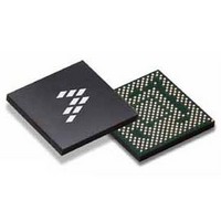
Manufacturer Part Number
SC900841JVKR2
Description
IC POWER MGT 338-MAPBGA
Manufacturer
Freescale Semiconductor
Specifications of SC900841JVKR2
Applications
PC's, PDA's
Operating Temperature
-40°C ~ 85°C
Mounting Type
Surface Mount
Package / Case
338-TBGA
Input Voltage
2.8 V to 4.4 V
Maximum Operating Temperature
+ 85 C
Minimum Operating Temperature
- 40 C
Lead Free Status / RoHS Status
Lead free / RoHS Compliant
Current - Supply
-
Voltage - Supply
-
Lead Free Status / Rohs Status
Lead free / RoHS Compliant
Available stocks
Company
Part Number
Manufacturer
Quantity
Price
Company:

Part Number:
SC900841JVKR2
Manufacturer:
Freescale Semiconductor
Quantity:
10 000


Table 25. RTC Control Registers Structure and Bit Description
Analog Integrated Circuit Device Data
Freescale Semiconductor
SCRATCH
Reserved
Reserved
Reserved
Reserved
TRIMVAL
OSCSTP
BKDET
IRQF
SIGN
POR
VRT
ADJ
UF
AF
3:0
6:0
7:3
7:1
5:0
4
5
6
7
7
0
1
2
0
6
Reserved
Update-Ended Interrupt Flag. Set after each update cycle.
X0 = UIE bit will not effect IRQF state
x1 = When UIE bit goes high, the IRQF bit goes high
Alarm Interrupt Flag. Indicates that the current time has matched the alarm time.
X0 = AIE bit will not effect IRQF state
x1 = When AIE bit goes high, the IRQF bit goes high
Fixed to 0
Interrupt Request Flag. IRQF = (AF&AIE) + (UF&UIE)
The interrupt request flag (IRQF) is set to a “1” when one or more of the following are true:
AF = AIE = “1”
UF = UIE = “1”
x0 = Above Equation is not true
x1 = Above Equation is true
Fixed to 000000
The Valid RAM and Time (VRT) bit indicates the condition of the contents of the RTC time and calendar registers . A
“0” appears in the VRT bit when the RTC registers have been reset. The processor program should set the VRT bit
after the time and calendar are initialized to indicate that the time and calendar are valid. The VRT bit can only be set
by reading register D.
Oscillator (32 kHz) Clock Stop Flag
x0 = XTAL Oscillator
x1 = Internal RC Oscillator
Coin Cell Backup Voltage Status
x0 = No change
x1 = Coin Cell below “low-voltage” threshold
When this bit is set to 1, the SW takes corresponding action for a coin cell well below the operating voltage, and clear
the BKDET in order to get ready for the next event.
RTC Reset Flag
x0 = No reset was detected
x1 = POR occurred
These bits shall not exert any control over the operation of the RTC, and are intended to be used as scratch pad
registers by the system controller. Their contents are erased on RTCPORB.
RTC Trim Enable Signal
x0 = Do Not Trim
x1 = Trim
Fixed to 0000000
6-Bit Trim Control
This is a number from 0 to 63 that represents the number of seconds to adjust out of every 64 seconds
RTC Calibration Sign Bit
x0 = Add
x1 = Subtract
RTCE (ADDR 0x1E - R/W - Default Value: 0x05)
TRIM (ADDR 0x20 - R/W - Default Value: 0x00)
ADJ (ADDR 0x1F - R/W - Default Value: 0x00)
RTCC (ADDR 0x1C - R - Default Value: 0x00)
RTCD (ADDR 0x1D - R - Default Value: 0x00)
CLOCK GENERATION AND REAL TIME CLOCK (RTC)
FUNCTIONAL DEVICE OPERATION
900841
59
Related parts for SC900841JVKR2
Image
Part Number
Description
Manufacturer
Datasheet
Request
R

Part Number:
Description:
Ultra-mobile Platform Pmic
Manufacturer:
Freescale Semiconductor, Inc
Datasheet:

Part Number:
Description:
Sc900 Programmable Penta Uldo With Reset And I2c Interface
Manufacturer:
Semtech Corporation
Datasheet:
Part Number:
Description:
Manufacturer:
Freescale Semiconductor, Inc
Datasheet:
Part Number:
Description:
Manufacturer:
Freescale Semiconductor, Inc
Datasheet:
Part Number:
Description:
Manufacturer:
Freescale Semiconductor, Inc
Datasheet:
Part Number:
Description:
Manufacturer:
Freescale Semiconductor, Inc
Datasheet:
Part Number:
Description:
Manufacturer:
Freescale Semiconductor, Inc
Datasheet:
Part Number:
Description:
Manufacturer:
Freescale Semiconductor, Inc
Datasheet:
Part Number:
Description:
Manufacturer:
Freescale Semiconductor, Inc
Datasheet:
Part Number:
Description:
Manufacturer:
Freescale Semiconductor, Inc
Datasheet:
Part Number:
Description:
Manufacturer:
Freescale Semiconductor, Inc
Datasheet:
Part Number:
Description:
Manufacturer:
Freescale Semiconductor, Inc
Datasheet:
Part Number:
Description:
Manufacturer:
Freescale Semiconductor, Inc
Datasheet:
Part Number:
Description:
Manufacturer:
Freescale Semiconductor, Inc
Datasheet:
Part Number:
Description:
Manufacturer:
Freescale Semiconductor, Inc
Datasheet: